Eureka AIR delivers breakthrough ideas for toughest innovation challenges, trusted by R&D personnel around the world.

Battery Plate Flash Dryer Oven With Self-Cleaning Feature

Inactive Publication Date: 2009-10-08
INT THERMAL SYST
View PDF16 Cites 13 Cited by
  • Summary
  • Abstract
  • Description
  • Claims
  • Application Information

AI Technical Summary

Benefits of technology

[0014]As the conveyor belt passes through the slide bed in the bottom of the lower supply duct, it will carry lead oxide dust and particles with it, thereby removing them from the lower supply duct and not allowing them to build up within the lower supply duct. By extending the slide bed to a point over a drawer, the lead oxide dust and particles will be deposited in the drawer by the movement of the conveyor belt. Thus, the self-cleaning flash dryer oven of the present invention will continuously clean out any lead oxide dust and particles contained in the lower supply duct, with no manual effort of the operator being required to do so.
[0015]The top side of the lower supply duct is also modified to have a gabled construction when viewed from either end of the lower supply duct. Nozzles are located in both sides of the top side of the lower supply duct. The gabled construction of the top side of the lower supply duct will act to direct at least some of the lead oxide dust and particles to either side of the lower supply ducts, with this portion of the lead oxide dust and particles then falling to the bottom of the interior of the self-cleaning flash dryer oven, where they will not substantially interfere with the flow of heated air within the self-cleaning flash dryer oven of the present invention. The lead oxide dust and particles located at the bottom of the interior of the self-cleaning flash dryer oven can periodically be cleaned out through access doors located in the sides of the self-cleaning flash dryer oven.
[0016]It may therefore be seen that the present invention teaches a self-cleaning flash dryer oven that includes an improved provision for the removal of lead oxide dust and particles which are deposited in the lower supply duct. The self-cleaning flash dryer oven of the present invention removes lead oxide dust and particles therefrom without the need for operator intervention to initiate or facilitate such removal of lead oxide dust and particles. The self-cleaning flash dryer oven of the present invention continuously removes the lead oxide dust and particles to prevent the buildup of any lead oxide dust and particles in the lower supply duct.
[0017]The self-cleaning flash dryer oven of the present invention accomplishes the removal of the lead oxide dust and particles from the lower supply duct without needing to be turned off, thereby precluding the necessity of taking it out of production. The self-cleaning flash dryer oven of the present invention also ensures that the removal of the lead oxide dust and particles from the lower supply duct does not in any way interfere with the supply of hot air through the lower supply duct to dry battery plates passing through the flash dryer oven. The lead oxide dust and particles removed from the lower supply duct are collected at a particular location from which they can periodically be removed and disposed of without stopping the operation of the flash dryer oven of the present invention.
[0018]The self-cleaning flash dryer oven of the present invention is of a construction which is both durable and long lasting, and which will require little or no maintenance to be provided by the user throughout its operating lifetime. The self-cleaning flash dryer oven of the present invention is also of inexpensive construction to enhance its market appeal and to thereby afford it the broadest possible market. Finally, all of the aforesaid advantages and objectives are achieved by the self-cleaning flash dryer oven of the present invention without incurring any substantial relative disadvantage.

Problems solved by technology

As the conveyor belt passes through the slide bed in the bottom of the lower supply duct, it will carry lead oxide dust and particles with it, thereby removing them from the lower supply duct and not allowing them to build up within the lower supply duct.

Method used


Image

  • Battery Plate Flash Dryer Oven With Self-Cleaning Feature
  • Battery Plate Flash Dryer Oven With Self-Cleaning Feature
  • Battery Plate Flash Dryer Oven With Self-Cleaning Feature

Examples


Embodiment Construction

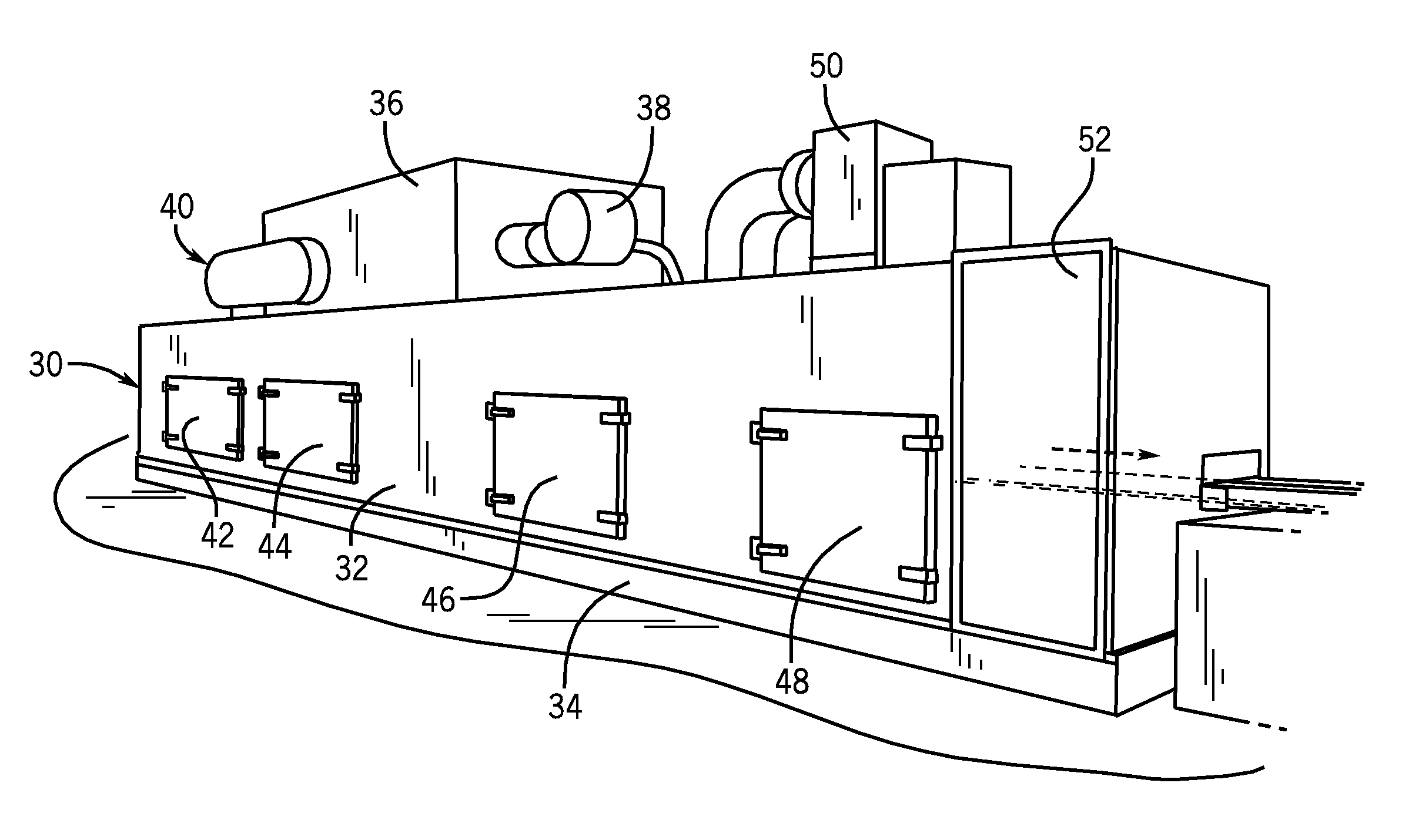
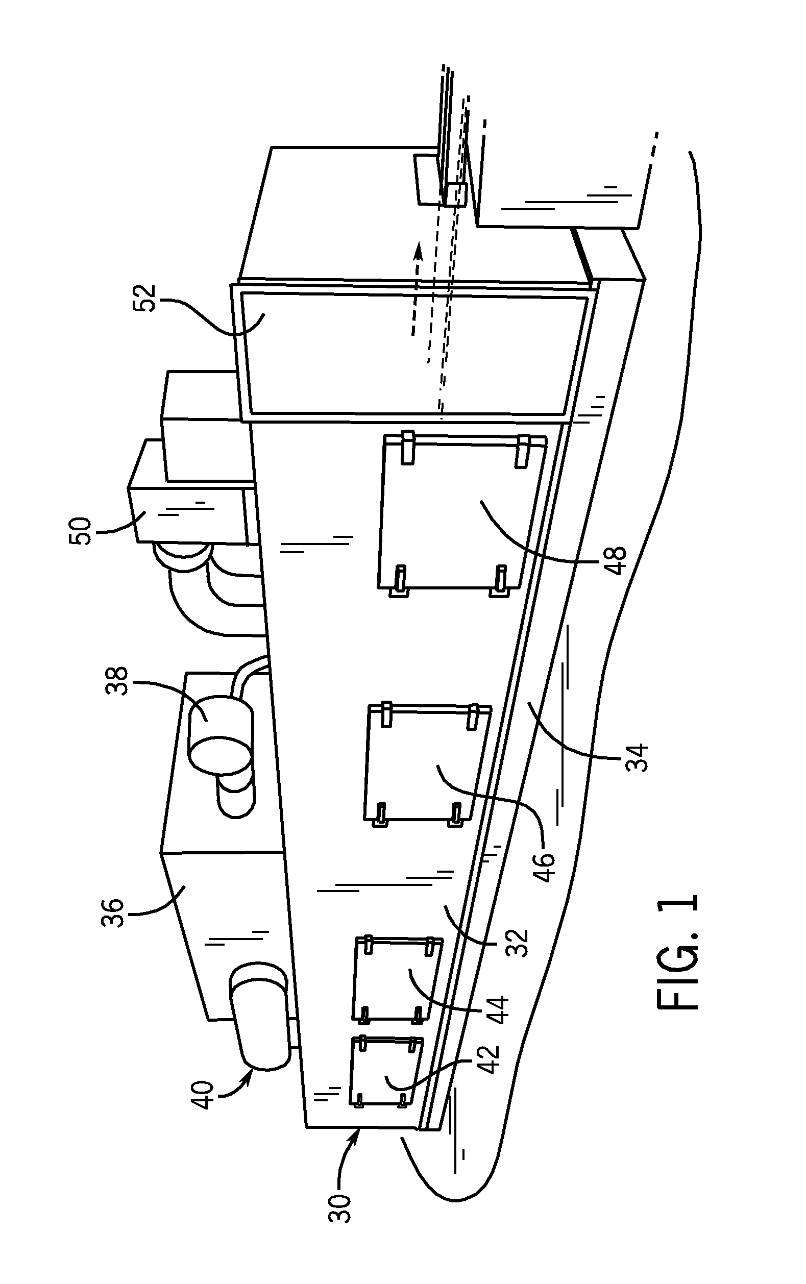
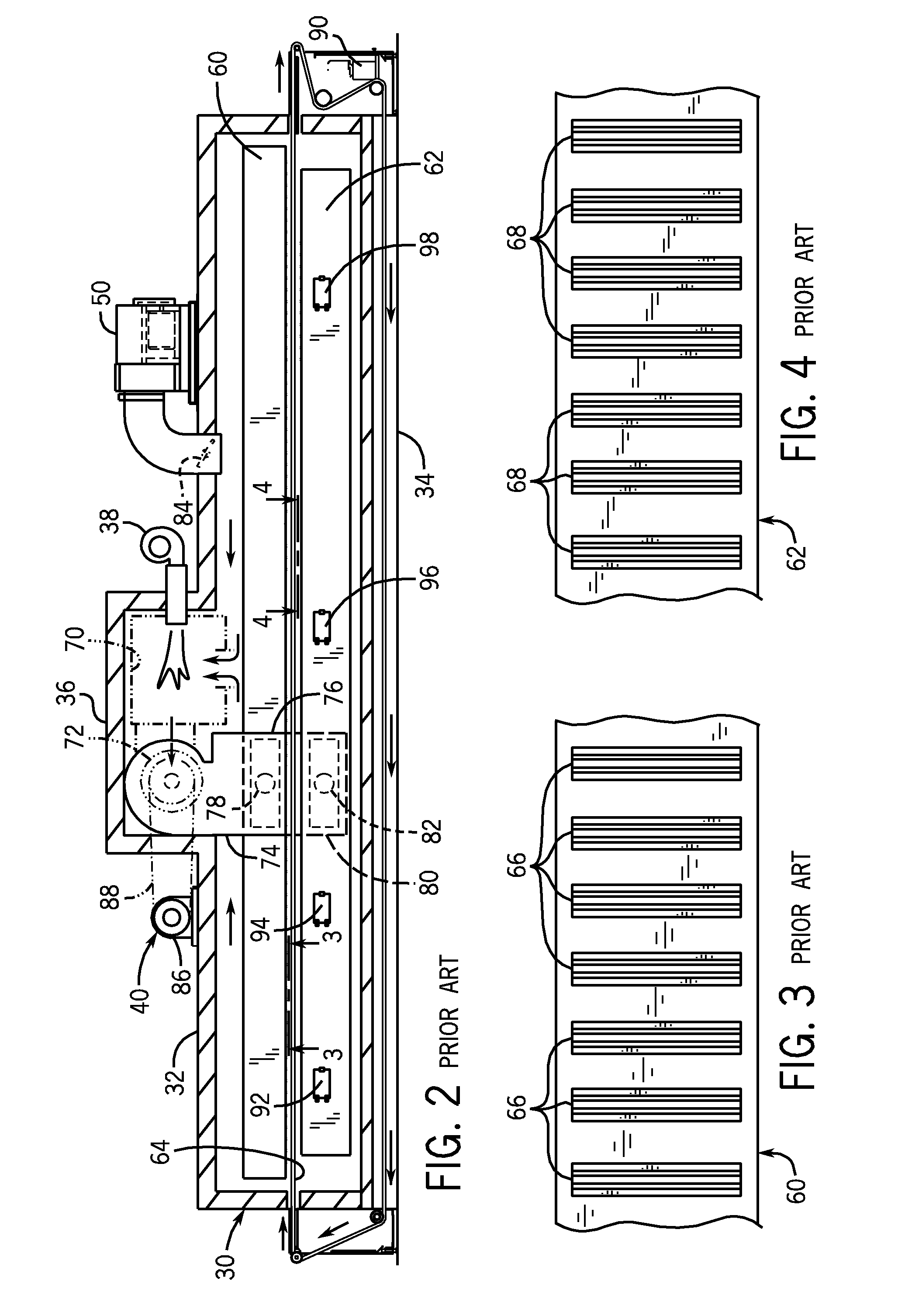
[0032]An exemplary embodiment of the self-cleaning flash dryer oven of the present invention will be presented herein. However, it is beneficial to first provide a brief discussion of the construction and operation of a conventional flash dryer oven, after which the points of departure therefrom by the self-cleaning flash dryer oven of the present invention may be discussed.

[0033]Referring first to FIG. 1, the exterior of a flash dryer oven 30 is illustrated from the perspective of its side and its outlet end. While the flash dryer oven 30 shown in FIG. 1 depicts a previously known flash dryer oven, it is also essentially identical in appearance from the outside thereof to the self-cleaning flash dryer oven of the present invention, as will become evident below in conjunction with the discussion of FIGS. 5 and 6. The flash dryer oven 30 has an oven housing 32 that is of rectangular configuration (and which is typically approximately thirty-one feet long by six feet wide by five feet...


PUM


Abstract

An improved flash dryer oven is disclosed which operates in a self-cleaning manner that continuously removes dust and debris from the oven, thereby preventing dust and debris from interfering with the hot air flow through the oven. A self-cleaning function is provided to the flash dryer oven by routing the conveyor belt through the lower supply duct on its return path to continuously clean out lead oxide dust and particles that are located within the lower supply duct. In addition, the lower supply duct has a gabled top that will direct some of the lead oxide dust and particles off of the lower supply duct instead of the lead oxide dust and particles falling through nozzles in the top of the lower supply duct and into the lower supply duct.

Description

BACKGROUND OF THE INVENTIONField of the Invention[0001]The present invention relates generally to industrial ovens, and more particularly to an improved flash dryer oven which operates in a self-cleaning manner that continuously removes dust and debris from the oven, thereby preventing dust and debris from interfering with the hot air flow through the oven.[0002]Flash dryer ovens have been used in the manufacture of battery plates for lead-acid storage batteries such as those commonly used in automobiles. Such lead-acid storage batteries generally comprise a plurality of individual cells, each of which contains two or more battery plates that are separated by thin, porous separators. The battery plates consist of generally rectangular conductive supporting grid structures that are typically made of lead or a lead alloy. The grid structures contain and support an active battery paste material consisting of a mixture of lead oxide, sulfuric acid, and water, with dry additives such as ...

Claims


Application Information

Patent Timeline
IPC IPC(8): F27B9/00
CPCF26B25/00F26B15/18
Inventor VETSCH, TERENCE L.
Owner INT THERMAL SYST
Why Eureka
Eureka Blog
Learn More