Automatic Cutting Device and Production Method for Beveled Product
a production method and cutting device technology, applied in auxillary welding devices, program control, instruments, etc., can solve the problems of long waiting time period, inability to make these two cutting sub-process stages succeed one another continuously in an efficient manner, and the accuracy of cutting is undesirably deteriorated
- Summary
- Abstract
- Description
- Claims
- Application Information
AI Technical Summary
Benefits of technology
Problems solved by technology
Method used
Image
Examples
first embodiment
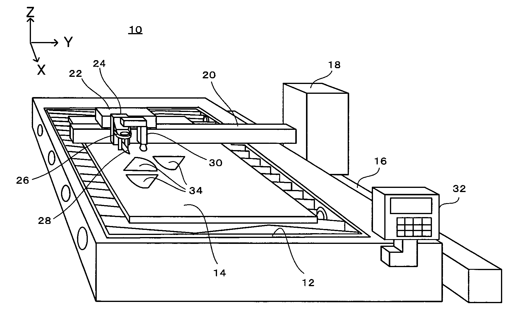
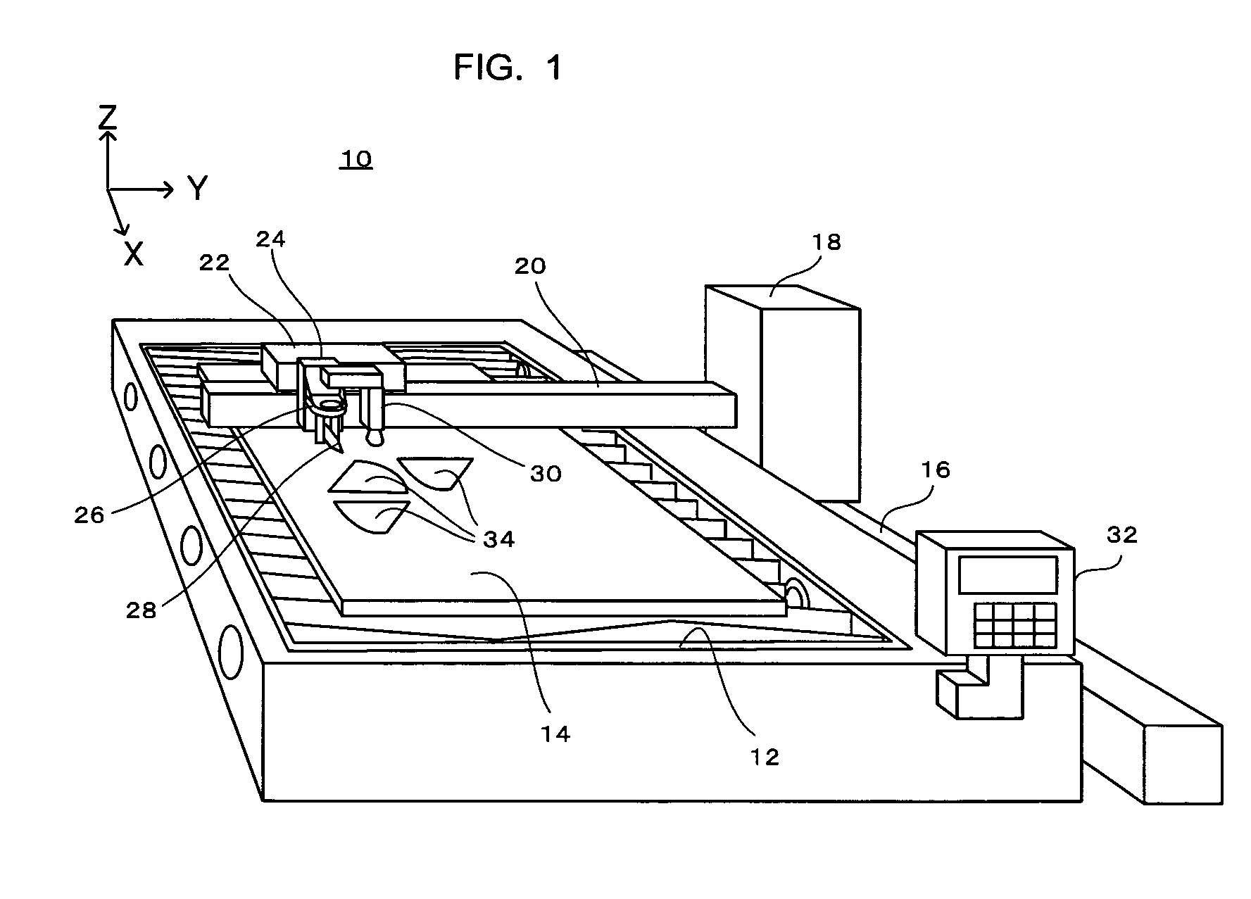
[0043]FIG. 1 shows the overall structure of the present invention, which is applied to a plasma cutting device.
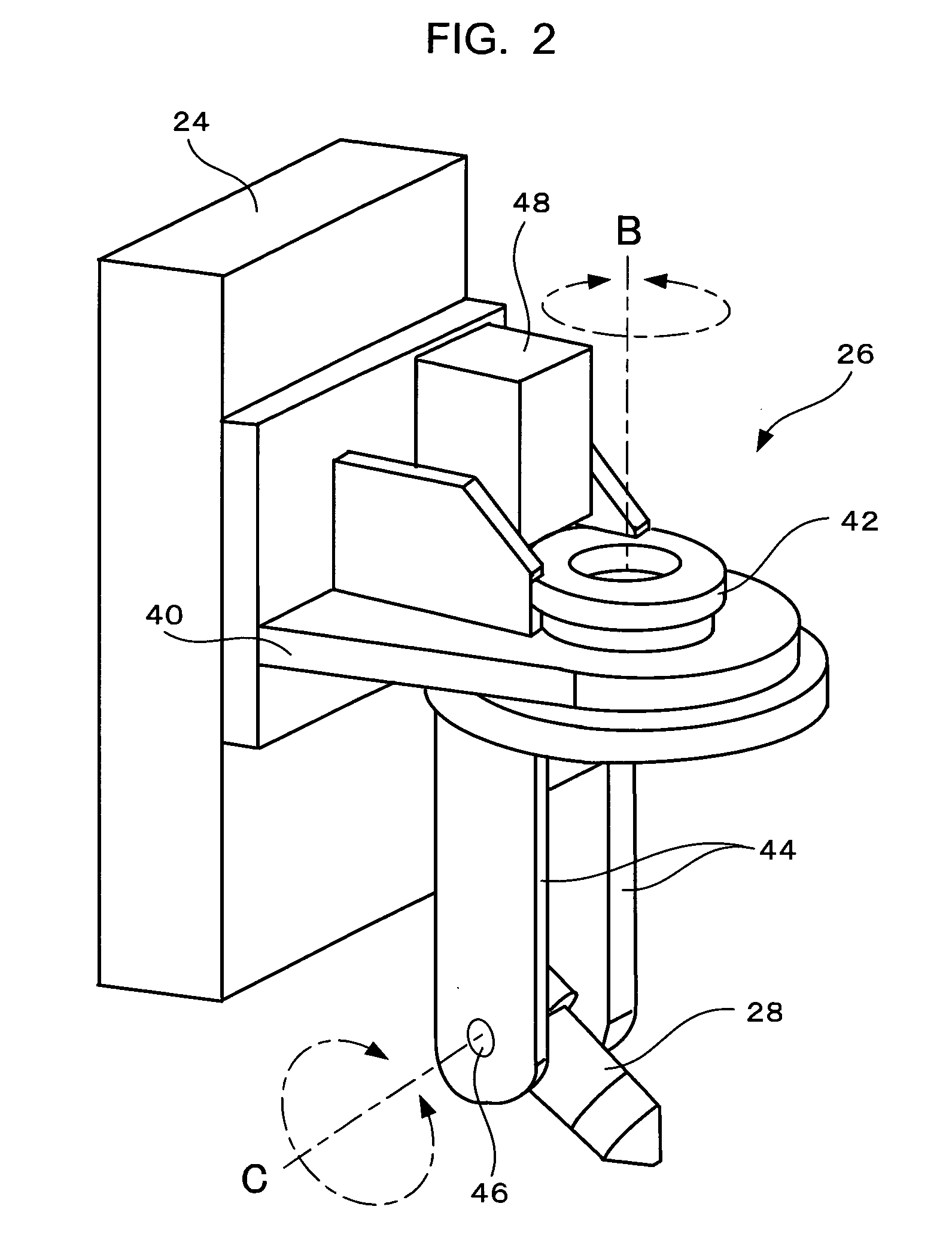
[0044]As shown in FIG. 1, the plasma cutting device 10 according to the first embodiment of the present invention comprises a table 12 which is shaped almost as a rectangular parallelepiped and which is mounted upon the floor, and a base material 14 (typically a steel plate) is mounted upon the upper surface of this table 12. In order to control the cutting position with respect to this base material 14, an orthogonal coordinate system is logically defined, having an X axis and a Y axis in the direction of the long side and the short side of the plane shape of the table 12 respectively, and moreover having a Z axis in the direction orthogonal to the upper surface of the table 12 (i.e. in the height direction). An X track 16 which is parallel to the X axis is installed upon the flank of the table 12, and a trolley 18 is carried upon this X track 16, so that the trolley 18 is...
second embodiment
[0084]FIG. 10 shows the way in which the image sensor 30 in this second embodiment is arranged, and the method of illuminating the image capture region of the image sensor 30.
[0085]As shown in FIG. 10, the image sensor 30 is fitted to the elevator 24 (the bracket 40) which holds the plasma torch 28, so that it shifts together with the plasma torch 28 in the X, Y, and Z directions. The image sensor 30 is arranged at a position which is sufficiently higher than the plasma torch 28, so that, when the base material 14 is being cut with the plasma torch 28, droplets of molten metal which jump up from the base material 14 do not come into contact with the image sensor 30. Two lamps 202 and 204 are also fitted upon the bracket 40, in positions on both sides of the image sensor 30. These two lamps 202 and 204 illuminate the image capture region 210 of the image sensor 30 on the surface of the base material 14, from both the sides of the image capture region 210.
[0086]Fouling (for example, s...
PUM
| Property | Measurement | Unit |
|---|---|---|
| pixel size | aaaaa | aaaaa |
| pixel size | aaaaa | aaaaa |
| angle | aaaaa | aaaaa |
Abstract
Description
Claims
Application Information
 - R&D
- Intellectual Property
- Life Sciences
- Materials
- Tech Scout
- Unparalleled Data Quality
- Higher Quality Content
- 60% Fewer Hallucinations
Browse by: Latest US Patents, China's latest patents, Technical Efficacy Thesaurus, Application Domain, Technology Topic, Popular Technical Reports.
© 2025 PatSnap. All rights reserved.Legal|Privacy policy|Modern Slavery Act Transparency Statement|Sitemap|About US| Contact US: help@patsnap.com


