
Plasma-cutting torch with integrated high frequency starter

a high-frequency starter and plasma cutting technology, applied in plasma welding apparatus, plasma technique, manufacturing tools, etc., can solve the problems of high voltage requirements, high design complexity, and high cost, and achieve the effect of reducing voltage requirements and reducing component interdependency

Inactive Publication Date: 2006-04-04
ILLINOIS TOOL WORKS INC
View PDF39 Cites 31 Cited by
  • Summary
  • Abstract
  • Description
  • Claims
  • Application Information

AI Technical Summary

Benefits of technology

[0010]The present invention is directed to a system for plasma cutting that overcomes the aforementioned drawbacks. Specifically, the present invention provides a system of HF starting a plasma cutting process with reduced voltage requirements. Additionally, the present invention reduces component interdependency and may be integrated with existing plasma cutting systems.

Problems solved by technology

While contact starting is a common method of initiating a plasma cutting process, it does present drawbacks.
Specifically, the moving electrode and / or nozzle are particularly susceptible to wear.
Furthermore, the designs are quite complex and are susceptible to misassembly, misalignment, or breakdown of the moving parts.
As such, the high-voltage transformer and coupling coil required to operate at such a voltage are relatively large, which can add to the size of the plasma-cutting system making portability cumbersome.
It is not uncommon for distance between the power source and torch to reach distances of over fifty feet, resulting in significant losses.
This problem is compounded as the distance from the power source to the torch varies as the cord connecting the two components is moved and stretched.
Furthermore, extended lengths of the power cord or cable may be susceptible to relatively harsh working conditions that may negatively affect the HF power being transferred to the torch.
Adding to these typically callous operating environments, the HF starting circuits typically generate a considerable amount of electrical noise.
Such noise can be particularly undesirable in sensitive manufacturing processes where electrical interference can impact the operability of the manufacturing process.
That is, because both the power source and the torch must be specifically tailored to the starting method, contact and HF starting power sources and torches may not be interchanged without modifications.

Method used


Image

  • Plasma-cutting torch with integrated high frequency starter
  • Plasma-cutting torch with integrated high frequency starter
  • Plasma-cutting torch with integrated high frequency starter

Examples


Embodiment Construction

[0020]The present invention is directed to a system for starting a plasma cutting process. Specifically, the present invention provides a system of HF starting a plasma cutting process with reduced voltage requirements. Additionally, the present invention reduces component interdependency and may be retrofitted to power sources configured for contact stating plasma cutters.

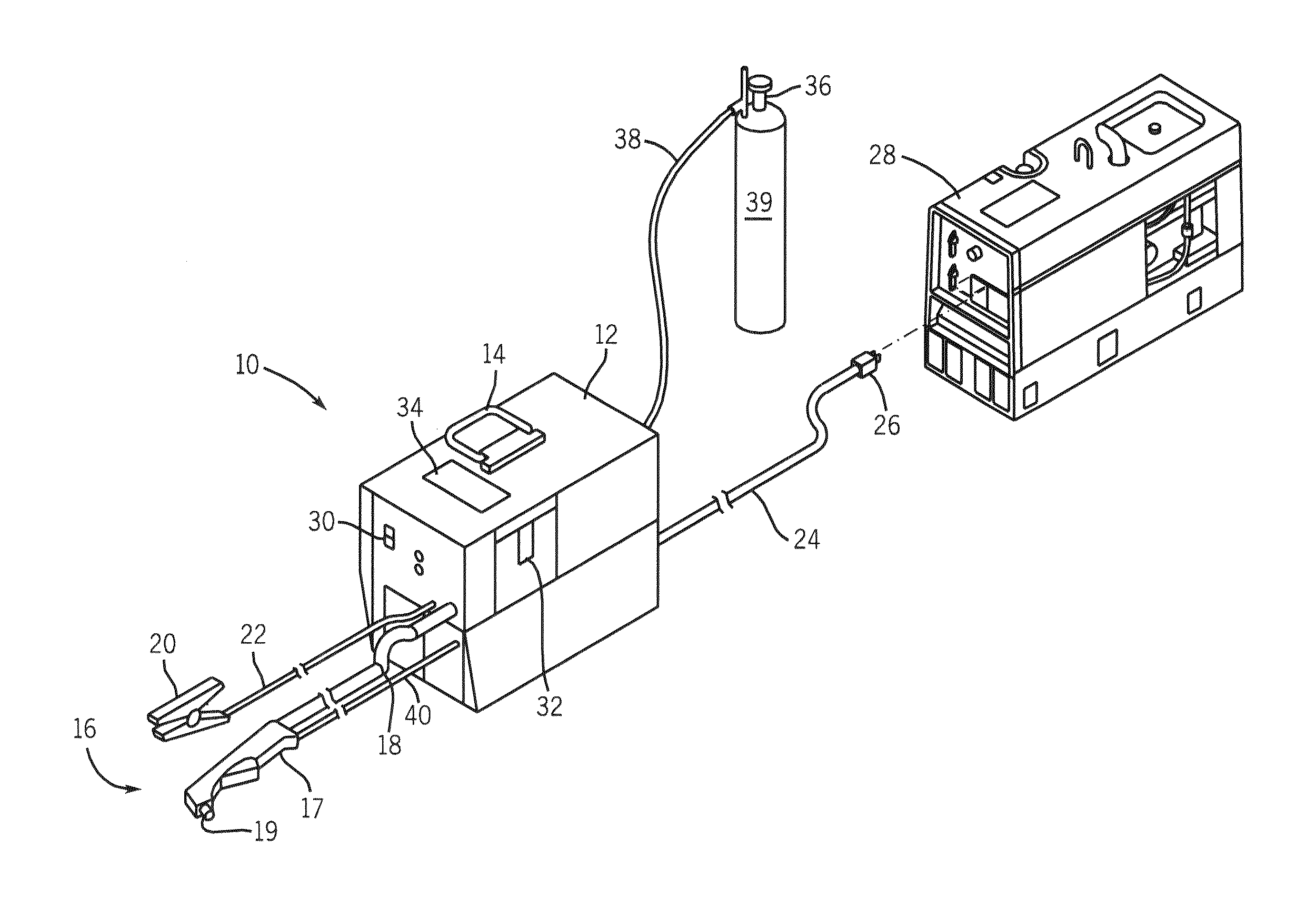
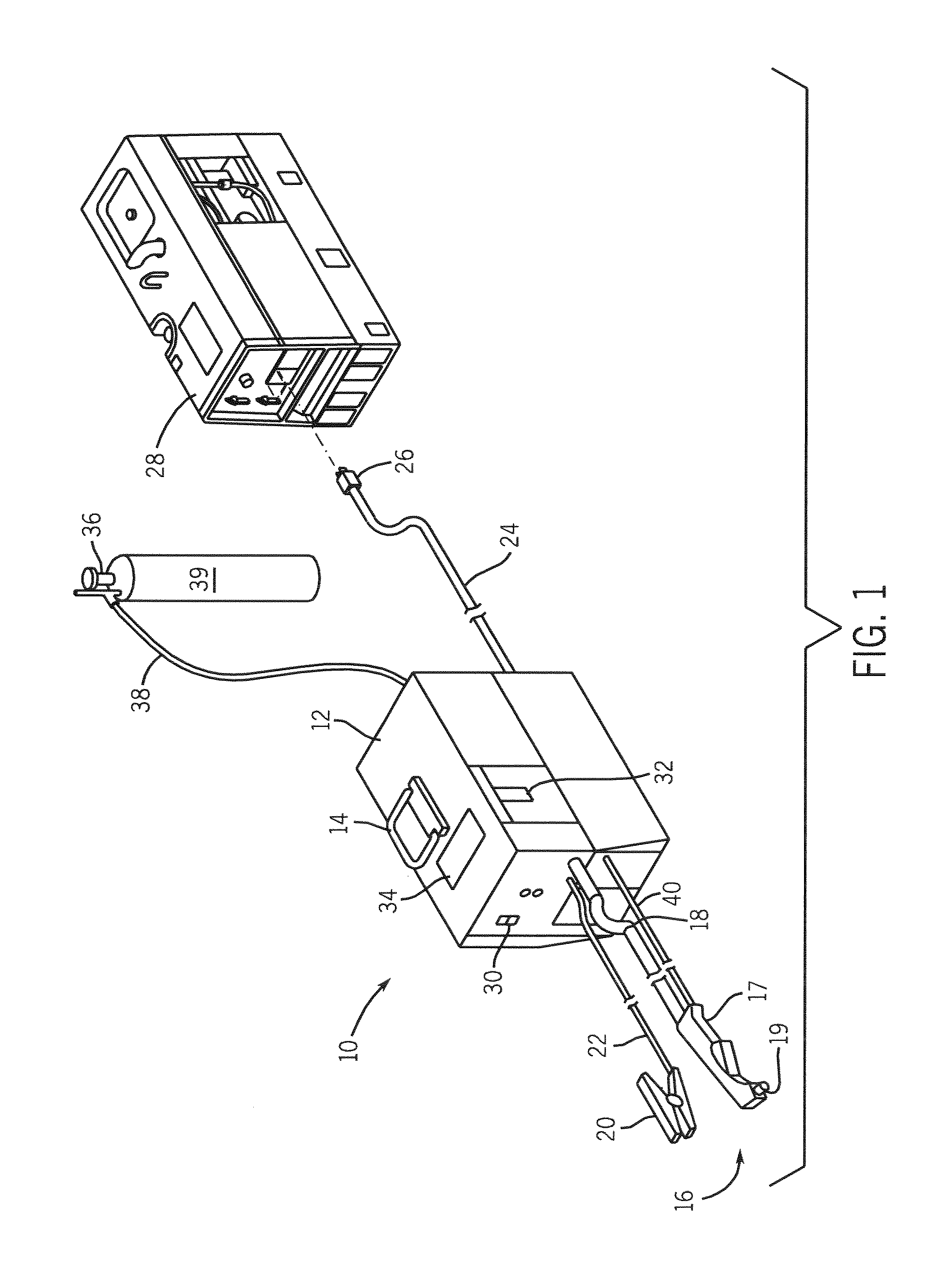
[0021]Referring to FIG. 1, a plasma cutting system 10 is shown. The plasma cutting system is a high voltage system with maximum open circuit output voltages ranging from approximately 230 Volts Direct Current (VDC) to over 300 VDC. The plasma cutting system 10 includes a power source 12 to condition raw power and regulate / control the cutting process. Specifically, the power source includes a processor that, as will be described, receives operational feedback and controls the plasma cutting system 10 accordingly. Power source 12 includes a lifting means, such as a handle 14 which effectuates transportation from one...


PUM

PropertyMeasurementUnit
distanceaaaaaaaaaa
open circuit output voltageaaaaaaaaaa
voltageaaaaaaaaaa

Abstract

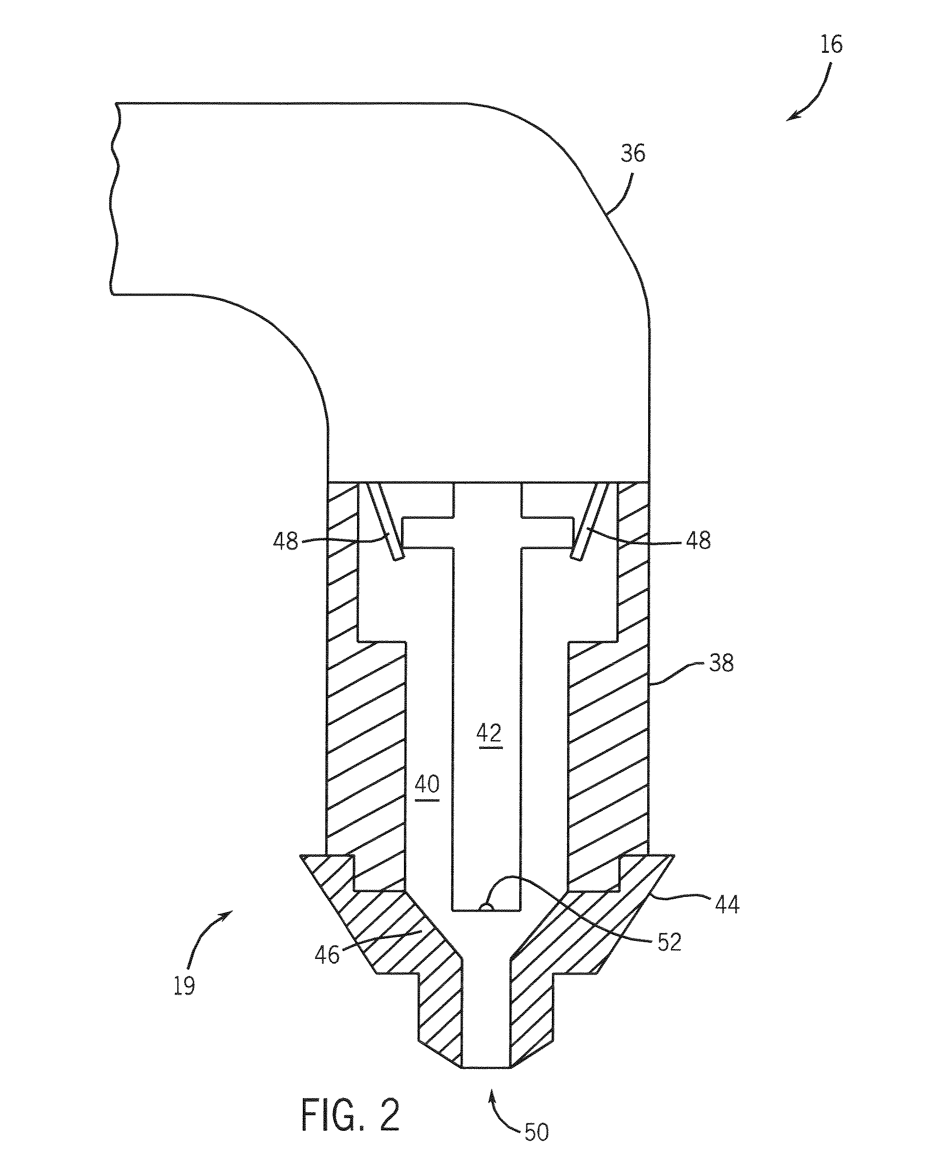
The present invention is directed to a system including a plasma cutting torch having an output electrode and a plasma cutter starting circuit configured to generate a pilot arc at the output electrode.

Description

BACKGROUND OF INVENTION[0001]The present invention relates generally to plasma cutting systems and, more particularly, to a system for plasma cutting wherein a high-frequency starting circuit is integrated within a plasma-cutting torch. As such, the amount of high frequency, high voltage power necessary for starting the plasma cutter is reduced and the amount of wires and circuitry exposed to the power source is reduced. Furthermore, the plasma-cutting torch may be retrofitted to power sources regardless of a startup configuration for which the power source was designed.[0002]Plasma cutting is a process in which an electric arc is used to cut a workpiece. Plasma cutters typically include a power source, a gas supply, and a torch. The torch or plasma torch is used to create and maintain the arc and plasma that perform the cutting. The plasma cutting power source receives an input voltage from a transmission power line or generator and provides an output voltage to a pair of output te...

Claims


Application Information

Patent Timeline
Patent Type & Authority Patents(United States)
IPC IPC(8): B23K9/00H05H1/36
CPCB23K10/00H05H1/36H05H2001/3426H05H1/3421
Inventor MATUS, TIM A.SOMMERFELD, TROY A.SCHNEIDER, JOSEPH C.ULRICH, JAMES F.
Owner ILLINOIS TOOL WORKS INC
Learn More