Electric circuit breaker, as well as plant, use and method where such is used

a circuit breaker and electric circuit technology, applied in the direction of air breakers, electronic commutation motor control, high-tension/heavy-dress switches, etc., can solve the problems of poor precision of spring-loaded operating devices, inability to tailor the movement of mobile contacts, and inability to control movement speed or acceleration

Inactive Publication Date: 2003-08-14
ABB (SCHWEIZ) AG
View PDF7 Cites 14 Cited by
  • Summary
  • Abstract
  • Description
  • Claims
  • Application Information

AI Technical Summary

Problems solved by technology

So the movement of the mobile contact cannot be tailored to the kind of opening or closing required in individual instances.
Nor can the movement's speed or acceleration be controlled.
The use of a spring-loaded operating device also incorporates poor precision, as the device is made of a relatively large number of components.
As a result of the large number of components, initial adjustment of the operating means, a complex and time-consuming procedure, is also necessary.
The poor precision in positioning the mobile contact and the absence of any facility for controlling the movement even means that damping devices may be needed at the end of the opening or closing process in order to prevent uncontrolled mechanical jarring.
Another disadvantage is the high noise level of a spring-loaded operating device.
Finally, a spring-loaded operating device has a relatively long delay from the time an operating command is issued until the mobile contact starts moving.
However, a hydraulic operating means has other disadvantages due to the presence of hydraulic fluid.
There is also a risk of hydraulic fluid leaking into the surroundings.
Hydraulically operated circuit breakers also have the problems of loud noise

Method used


Image

  • Electric circuit breaker, as well as plant, use and method where such is used
  • Electric circuit breaker, as well as plant, use and method where such is used
  • Electric circuit breaker, as well as plant, use and method where such is used

Examples


Embodiment Construction

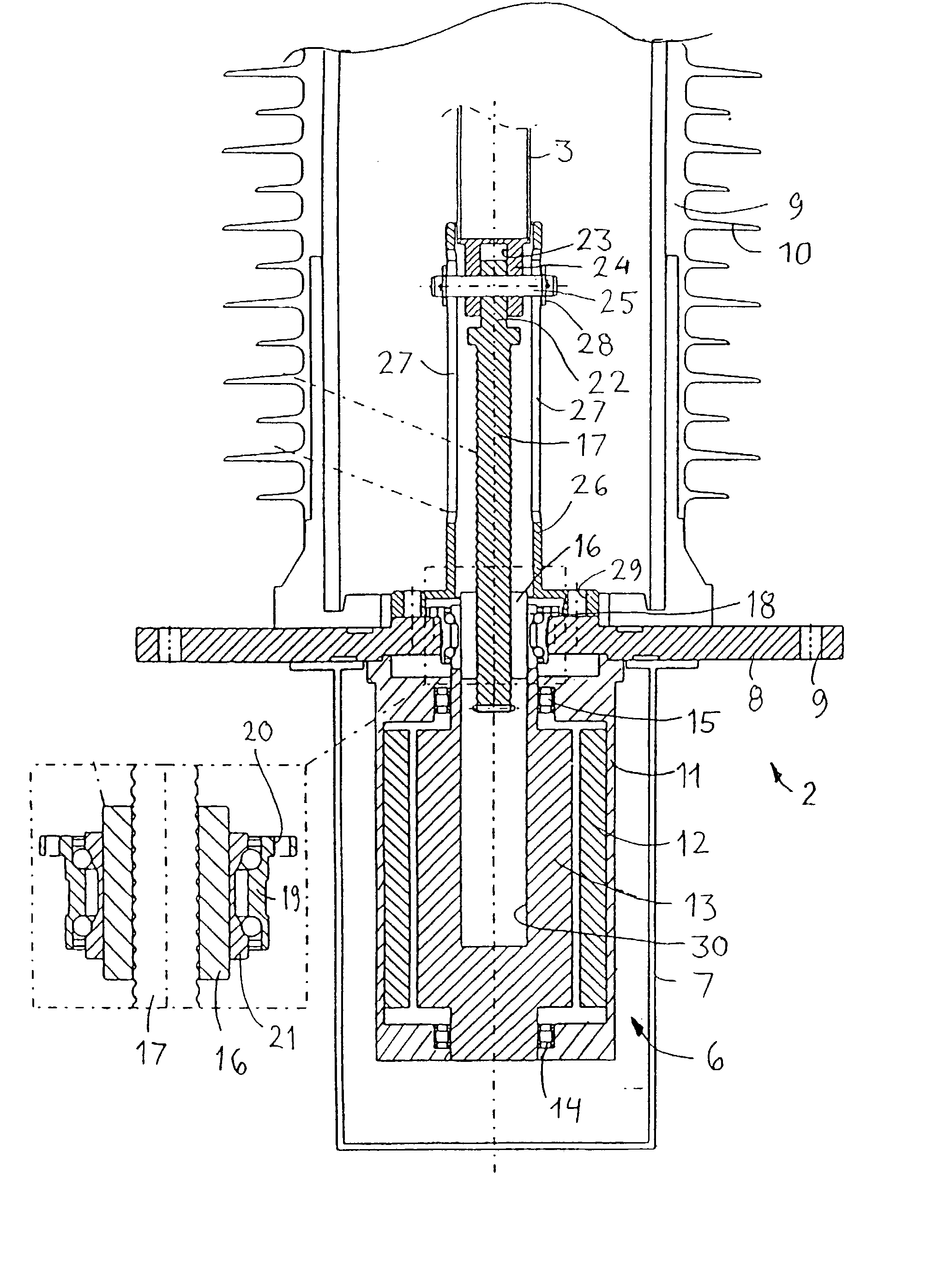
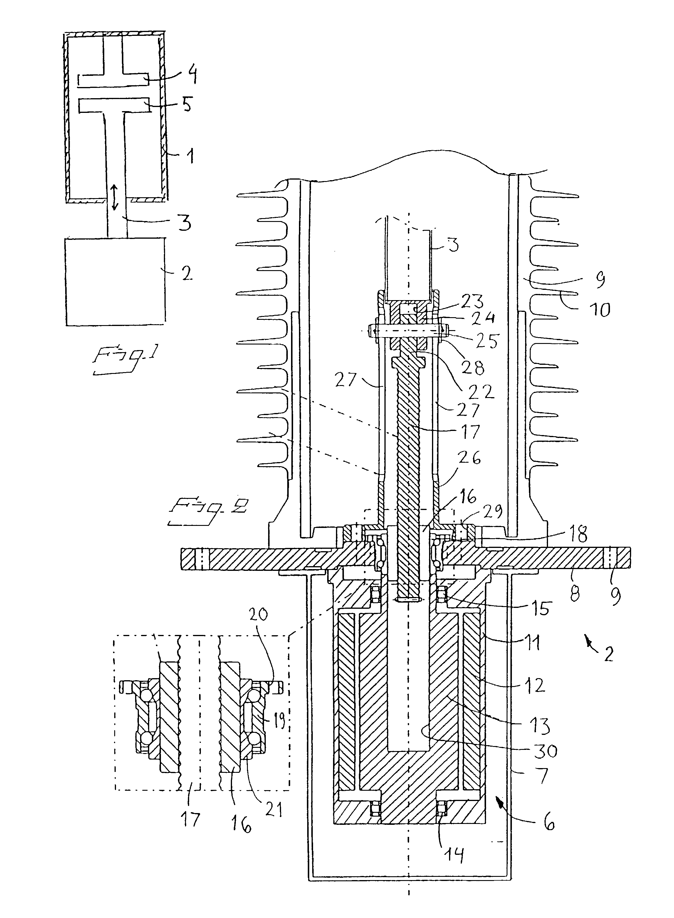
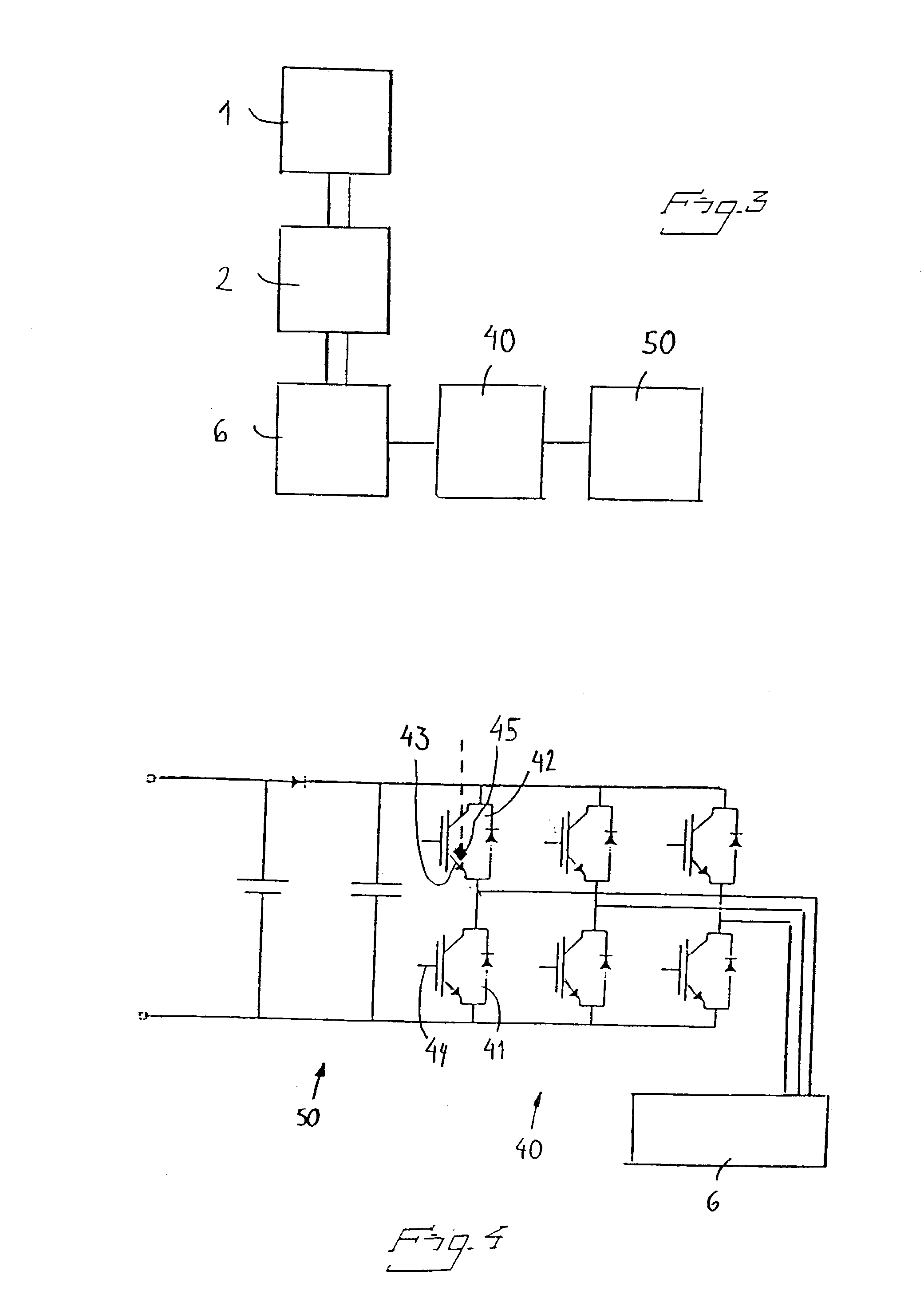
[0036] FIG. 1 schematically illustrates the principle of an electric circuit breaker. It consists of a breaker chamber 1, an operating means 2 and an operating rod 3. A stationary contact 4 and a mobile contact 5 are arranged in the breaker chamber. Each of the contacts is electrically connected to a separate line. In normal conditions, the contacts 4, 5 are in contact with one another, and current is conducted from one line to the other line through the circuit breaker. When the current must be broken for some reason, e.g. because of short-circuit currents caused by a fault, the mobile contact 5 is rapidly withdrawn from the stationary contact 4. An arc initially develops between the contacts and is extinguished by a flow of insulating gas shortly after the contacts have separated. When the current is subsequently closed, the mobile contact 5 is again forced into contact with the stationary contact 4. Breaking and closing can be manual or automatic. Turning the circuit breaker ON a...


PUM


Abstract

The invention relates to an electric circuit breaker. The circuit breaker comprises at least one mobile contact with operating means (2) for operating the same. An electric motor (6) is arranged for driving the operating means (2). The motor (6) is powered from a current source (50) via a current converter (40). According to the invention, the motor (6) and/or current converter (40) are greatly under-dimensioned in relation to the output the current converter is designed to deliver. This is possible because the operating duration is so brief. Under-dimensioning results in extensive cost-savings. The invention also relates to an electric plant equipped with such a circuit breaker. The invention further relates to the use of such a circuit breaker and a method for breaking electric current in the corresponding fashion.

Description

[0001] According to a first aspect, the present invention relates to an electric circuit breaker of the kind set forth in the preamble to claim 1. The circuit breaker is accordingly driven by an electric motor. A current converter is connected between the motor and the current source supplying power to the motor. The second, third and fourth aspects of the invention relate to an electric plant equipped with such a circuit breaker, to the use of such an electric circuit breaker and to a method for breaking an electric current.[0002] Circuit breakers of this kind are used in electric plants, such as switching stations, for breaking the power when necessary. A circuit breaker must be able to break and close normal power loads, but it must in particular be capable of rapidly breaking the short-circuit current arising when a fault occurs in the system. A circuit breaker's main components are the breaker chamber and the system for operating the same. Breaking and closing the current is ac...

Claims


Application Information

Patent Timeline
IPC IPC(8): H01H33/36H02P6/00
CPCH02P6/00H01H33/36H02P6/32
Inventor MAGNUSSEN, FREDDYKJAER, PHILIPVALDEMARSSON, STEFAN
Owner ABB (SCHWEIZ) AG
Why Eureka
Try Eureka