DC Distribution System

a distribution system and direct current technology, applied in the direction of constant-current supply dc circuits, instruments, process and machine control, etc., can solve the problems of requiring dc operation and emitting diodes

Active Publication Date: 2009-10-08
ENOCEAN
View PDF13 Cites 21 Cited by
  • Summary
  • Abstract
  • Description
  • Claims
  • Application Information

AI Technical Summary

Benefits of technology

[0005]A DC lighting system according to one non-limiting embodiment includes a DC power source operable to distribute a DC voltage throughout at least one environment, and at least one controller operable to selectively couple a DC lighting source to the DC voltage in response to a control signal.
[0006]A me

Problems solved by technology

Some loads, however, such as light-emitting

Method used


Image

  • DC Distribution System
  • DC Distribution System
  • DC Distribution System

Examples


Embodiment Construction

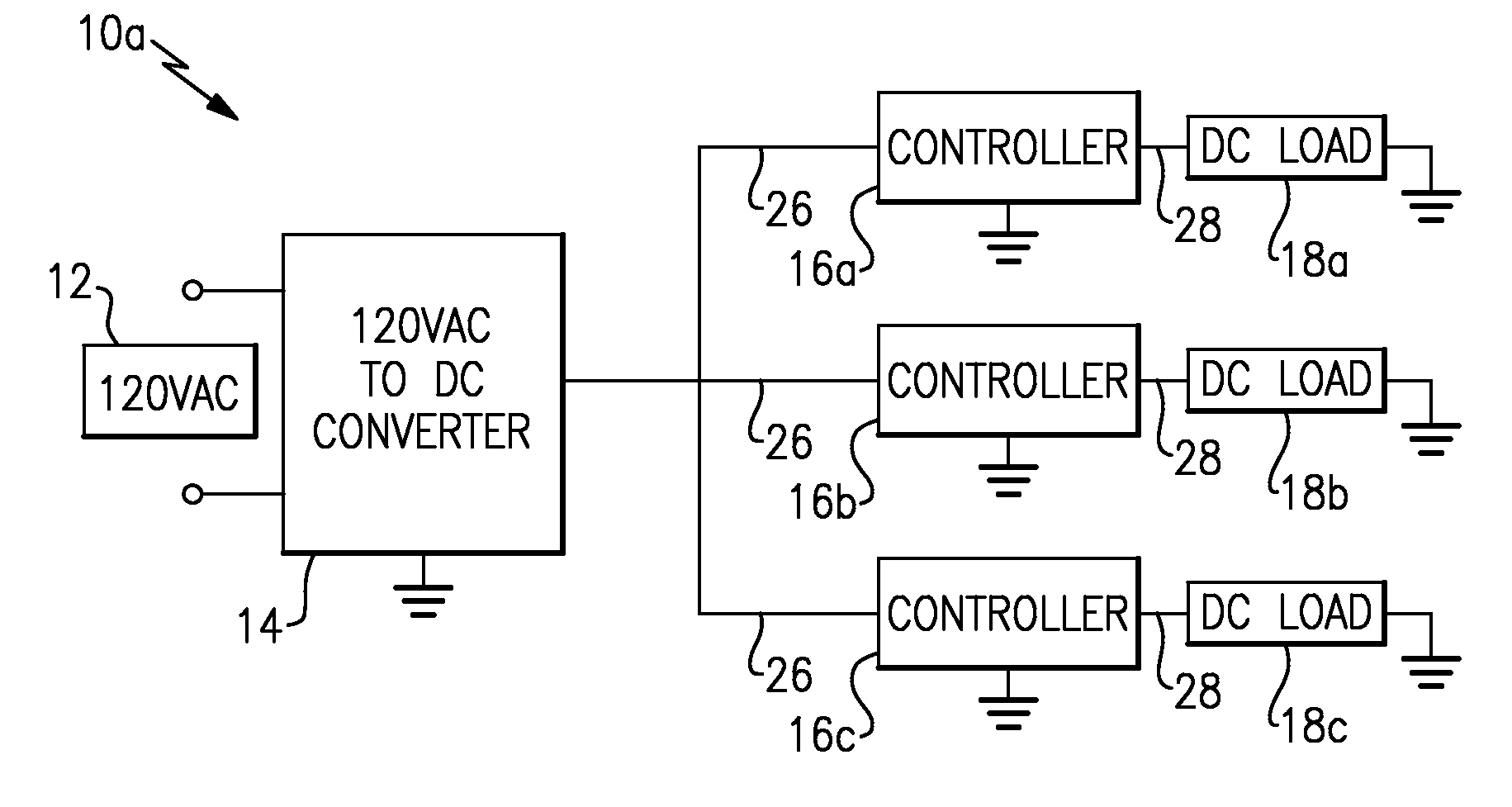
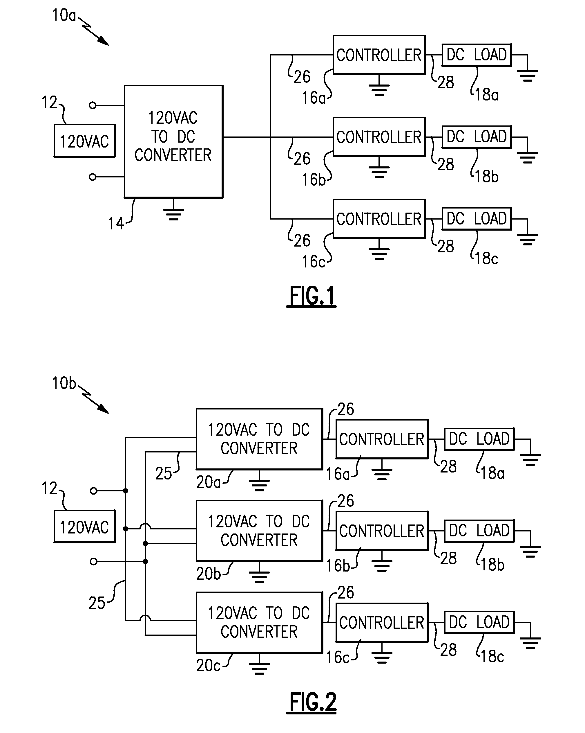
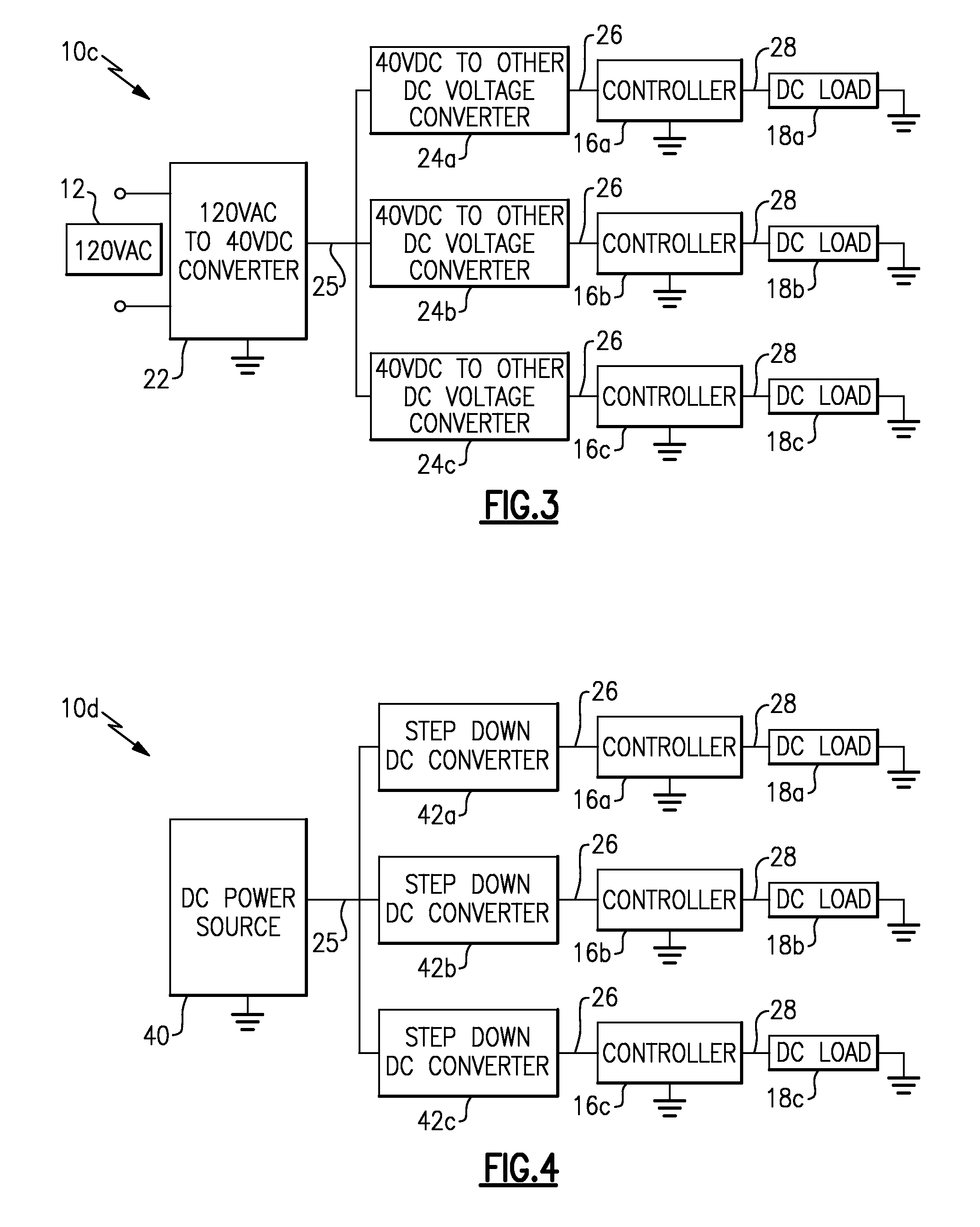
[0016]FIGS. 1-5 schematically illustrate a plurality of DC distribution systems 10a-e. FIG. 1 schematically illustrates a first DC distribution system 10a that includes an AC power source 12 and a power converter 14 coupled to the AC power source 12. The power converter 14 is operable to convert an AC input voltage from the AC power source 12 to a DC voltage.

[0017]Throughout this application an example AC input voltage of 120 VAC is illustrated. However, it is understood that other AC input voltages could be used. For example, 220 VAC is commonly used in Europe, and could be used with any of the disclosed systems 10a-e. The power converter 14 supplies power throughout at least one structure (see, e.g. FIG. 7) via a plurality of power lines 26 to a plurality of controllers 16a-c.

[0018]Each controller 16 is coupled to at least one DC load 18 via power lines 28. In one example the DC loads 18 include lighting loads (e.g. luminaires having LEDs). Of course, other DC lighting loads, and...


PUM


Abstract

A direct current power system according to one non-limiting embodiment includes a direct current power source operable to distribute a direct current voltage throughout at least one structure, and at least one controller operable to selectively couple a direct current load to the direct current voltage in response to a wireless signal from an energy-harvesting switch.

Description

BACKGROUND OF THE INVENTION[0001]The application claims priority to U.S. Provisional Application No. 61 / 042,449 which was filed on Apr. 4, 2008.[0002]This application relates to power distribution systems, and more particularly to a direct current (“DC”) distribution system.[0003]Electrical systems for buildings, such as residential buildings, are designed for alternating current (“AC”) and AC loads. Some loads, however, such as light-emitting diodes (“LEDs”), may require DC to operate. Existing LED lighting solutions have incorporated a substantial amount of electronics in a LED lamp to convert AC to DC to power the LED lamp. Other DC loads require AC adapters plugged into electrical outlets that perform an AC to DC conversion.SUMMARY OF THE INVENTION[0004]A DC power system according to one non-limiting embodiment includes a DC power source operable to distribute a DC voltage throughout at least one environment, and at least one controller operable to selectively couple a DC load t...

Claims


Application Information

Patent Timeline
IPC IPC(8): H05B37/02H02J1/00H02J1/04
CPCH02J1/14H02J13/0003H05B41/28H05B37/0263H02M2001/008H05B47/185H02M1/008H02J1/08H02J13/00022H05B47/19H02J13/00032H02J1/002
Inventor BARNETT, THOMAS ALANLOTT, JEFFREYXU, JIAN
Owner ENOCEAN
Why Eureka
Try Eureka