
Switched capacitance method for the detection of, and subsequent communication with a wireless transponder device using a single antenna

a wireless transponder and capacitance technology, applied in the field of rfid systems, can solve the problems of high power demand of data transaction mode, particularly undesirable condition, and rapidly deplete the power supply of the reader, and achieve the effect of reducing the amount of energy consumed by the reader and increasing power consumption

Active Publication Date: 2009-10-08
ASSA ABLOY AB
View PDF37 Cites 25 Cited by
  • Summary
  • Abstract
  • Description
  • Claims
  • Application Information

AI Technical Summary

Benefits of technology

[0013]Since only ping or impulse signals are transmitted by the reader during the detection mode, the reader runs at a very low duty cycle and a variable repetition rate for the duration of the detection mode. Consequently, the above-described technique enables the reader to operate with a relatively low average power consumption to avoid accelerated dissipation of the reader power supply while maintaining a rapid response time for transponder detection.
[0016]In accordance with at least some embodiments of the present invention, a reader is provided that can utilize a single RFID antenna to carry data to / from the reader from / to a credential in a transaction mode, as well as detect credentials in a detection mode. The detection mode may be operated according to a low power consumption method while sharing the same antenna. Readers utilizing embodiments of the present invention may be capable of consuming about 68 mA hours over the course of a year of operation. Accordingly, the reader detection function alone may be operated for over 30 years on an amount of energy typically stored in 4 AA batteries. Even if the reader is operating with an external power source, such as from a power outlet, the effective power consumption can be reduced.
[0019]In accordance with at least some embodiments of the present invention, the antenna may be connected to the tuning and driver circuits via a 4-wire interface. This antenna can be remoted and / or be swapped for a similar antenna. Alternatively, a 2-wire interface may be used to connect the antenna to the tuning and driver circuits. In this case, the reader and antenna form a pair. It is thus one aspect of the present invention to provide a reader that can operate a 2 or 4 wire antenna for detecting and communicating with transponders around of the range of about 0 to 12 inches. Lower power consumption by the reader may be achieved by the use of specific gates in any IC transitioning together. Thus, internal instability is essentially eliminated while operating in this lower power method.
[0021]Alternatively, two transponders may be designed to operate at significantly different carrier frequencies (i.e., 125 kHz and 13.56 MHz). In this example, the reader may be adapted to operate in the detection mode such that it can attempt to detect a transponder operating at the lower frequency and the (if no low-frequency transponder was detected) attempt to detect a transponder operating at the higher frequency. The reader may continue to toggle between the high and low frequencies until a transponder is detected at one of those frequencies, in which case the reader will then alter it's mode of operation to transact with the detected transponder at it's carrier frequency. This switching can be facilitated by multiple NFETs and capacitors across the antenna and ground.
[0022]One circuit that can be used in accordance with at least some embodiments of the present invention may include two NFETs with common drains and opposing body diodes so that the source of one NFET is grounded and the source of the other NFET connects to the capacitance that is being switched. This particular type of circuit may afford a greater isolation capability for the antenna.
[0024]Once the transaction between the reader and transponder has completed, the reader will re-initiate the detection mode where detection impulses or pings are periodically sent into the space surrounding the reader. One interesting aspect of the present invention is that the reader can review subsequently received responses while accounting for the transponder that was previously detected. Accordingly, the reader will not necessarily try and initiate a second transaction with the previously detected transponder as long as that transponder is not placed closer to the reader. If the previously detected transponder is kept in substantially the same place or moved slightly away from the reader, the reader will determine that the detected change in the response ring is due to the presence of the previously detected transponder. Thus, the reader will continue to initiate periodic detection impulses or pings. If, however, another transponder or object is introduced to the field that further alters the response ring, then the reader will initiate the transaction mode for the newly detected transponder or object. One advantage offered by this particular method is that the reader is prevented from initiating the transaction mode, which has a relatively higher power consumption than the detection mode, while a transponder is being withdrawn from the proximity of the reader. This ultimately reduces the amount of energy consumed by the reader.

Problems solved by technology

Although a reader can continuously operate in the data transaction mode, the functions of the data transaction mode typically have a relatively high power demand, which can rapidly deplete the power supply of the reader.
This condition is particularly undesirable when the reader is powered by a self-contained portable power supply, such as a small disposable or rechargeable battery, which has a finite life.
In particular, inductive coupling of the reader antenna to the nearby transponder antenna causes a change in the response on the reader antenna.

Method used


Image

  • Switched capacitance method for the detection of, and subsequent communication with a wireless transponder device using a single antenna
  • Switched capacitance method for the detection of, and subsequent communication with a wireless transponder device using a single antenna
  • Switched capacitance method for the detection of, and subsequent communication with a wireless transponder device using a single antenna

Examples


Embodiment Construction

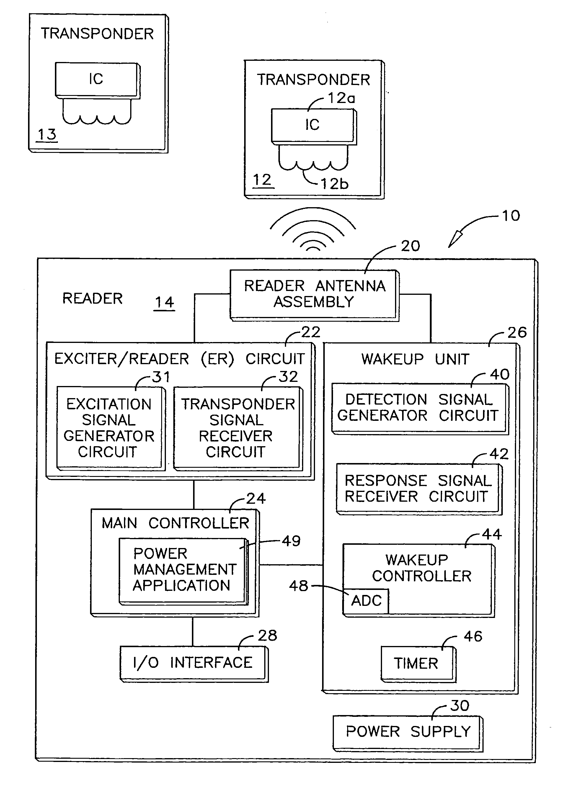
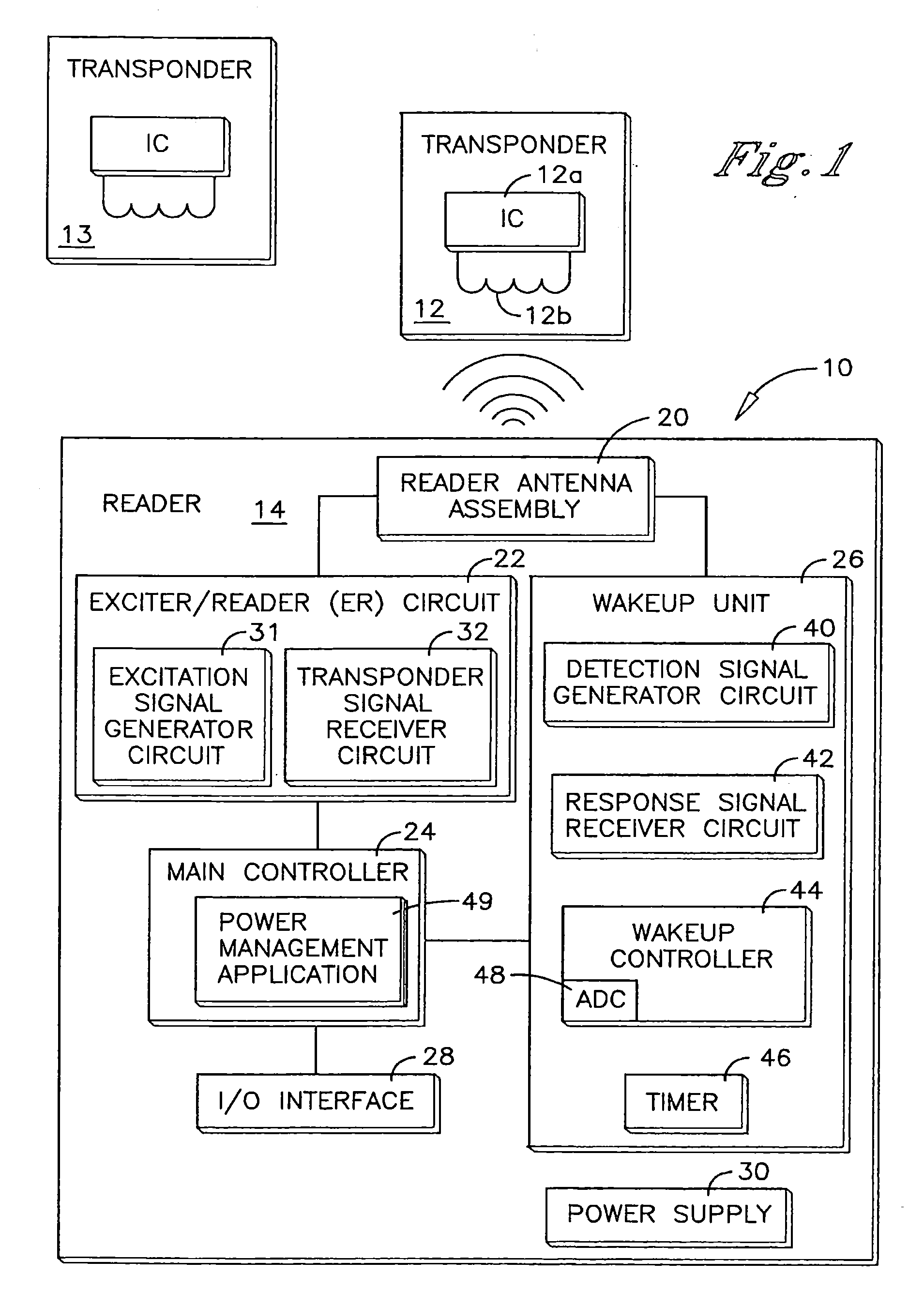
[0036]The invention will be illustrated below in conjunction with an exemplary reader device. Although well suited for use with, e.g., a system using access control readers and / or transponders, the invention is not limited to use with any particular type of access control system or configuration of system elements. Those skilled in the art will recognize that the disclosed techniques may be used in any RF system n which it is desirable to minimize power consumption of the reader.

[0037]The exemplary systems and methods of this invention will also be described in relation to analysis software, modules, and associated analysis hardware. However, to avoid unnecessarily obscuring the present invention, the following description omits well-known structures, components and devices that may be shown in block diagram form, are well known, or are otherwise summarized.

[0038]For purposes of explanation, numerous details are set forth in order to provide a thorough understanding of the present i...


PUM


Abstract

A transponder detector is provided with capabilities for detecting the presence and type of a transponder in its read range while operating at low power and also using a common antenna for detecting and executing data transactions with transponders.

Description

CROSS-REFERENCE TO RELATED APPLICATIONS[0001]This Application claims the benefit of U.S. Provisional Application No. 61 / 041,358, filed Apr. 1, 2008, the entire disclosure of which is hereby incorporated herein by reference.TECHNICAL FIELD[0002]The present invention relates generally to RFID systems and, more particularly, to the construction and operation of a transponder detector capable of detecting and reading transponders with the same antenna.BACKGROUND OF THE INVENTION[0003]Radio frequency identification (RFID) systems typically include at least one reader and a plurality of transponders, which are commonly termed credentials, cards, tags, or the like. Each transponder is an active or passive radio frequency communication device which is directly attached to or embedded in an article to be identified or otherwise characterized by the reader. Alternatively, the transponder is embedded in a portable substrate, such as a card, tag, or the like, carried by a person or an article t...

Claims


Application Information

Patent Timeline
IPC IPC(8): H04Q5/22
CPCG06K7/10128G06K7/0008
Inventor BORCHERDING, ERIC J.
Owner ASSA ABLOY AB
Learn More