Driving circuit for a liquid crystal display

a technology of driving circuit and liquid crystal display, which is applied in the direction of electric digital data processing, instruments, computing, etc., can solve the problem of limiting the extent to which the refresh rate could be reduced, and achieve the effect of reducing power consumption

Inactive Publication Date: 2009-10-08
SONY CORP
View PDF10 Cites 45 Cited by
  • Summary
  • Abstract
  • Description
  • Claims
  • Application Information

AI Technical Summary

Benefits of technology

[0008]An objective of the present application is to allow the driving of...

Problems solved by technology

According to earlier techniques, there was a limit to the extent to which the refresh rate could be red...

Method used


Image

  • Driving circuit for a liquid crystal display
  • Driving circuit for a liquid crystal display
  • Driving circuit for a liquid crystal display

Examples


Embodiment Construction

[0041]The invention will be more clearly understood from the following description, given by way of example only, with reference to the accompanying drawings.

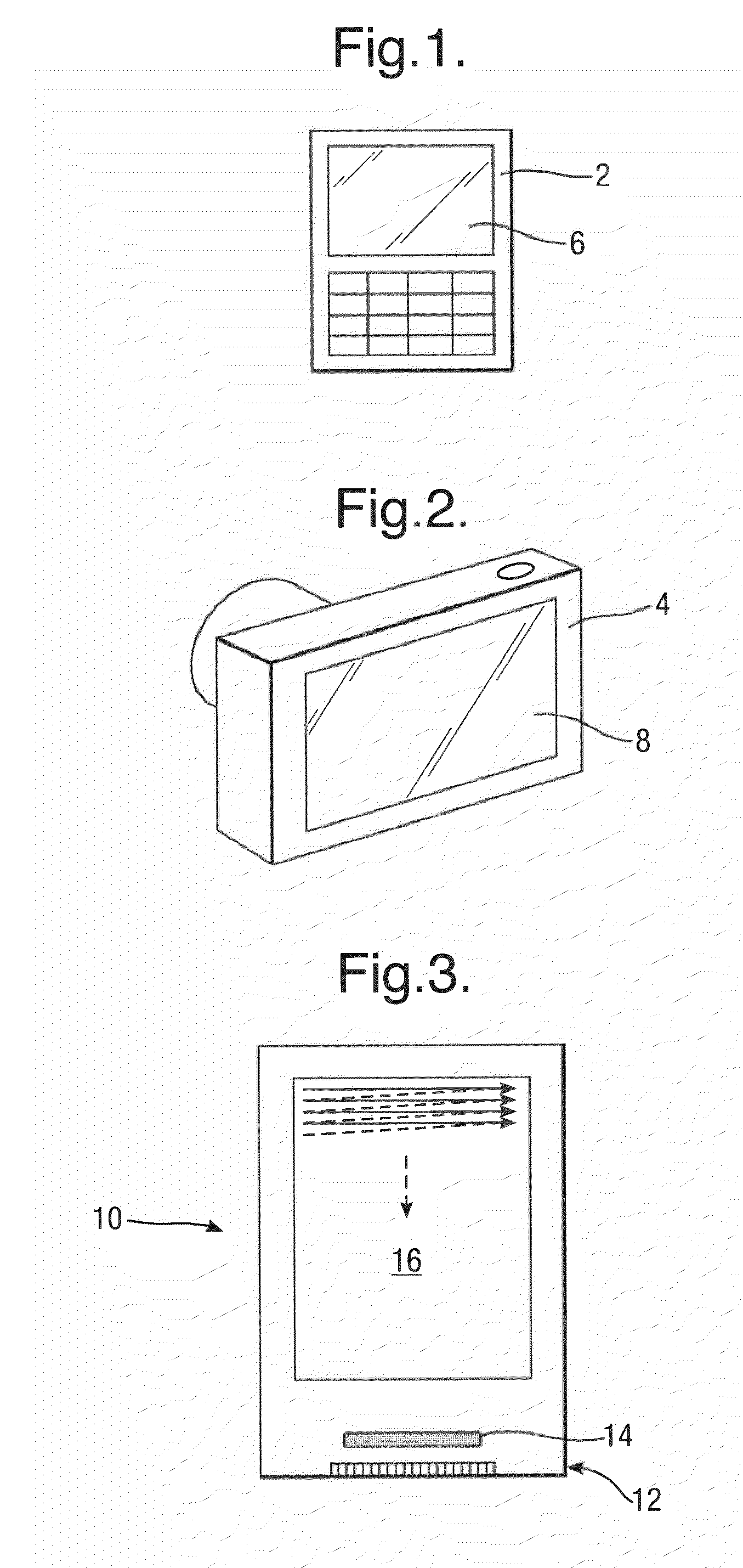
[0042]The present invention is applicable to LCD (Liquid Crystal Display) modules such as are used in mobile telephone devices or digital cameras, for instance as illustrated respectively in FIGS. 1 and 2. Other examples include portable gaming devices and personal media players. The present invention could be applied to any LCD, including those with LCD driving circuits formed on the display panel of the LCD module itself.

[0043]In the mobile telephone device 2 of FIG. 1 and the digital camera 4 of FIG. 2, respective LCD modules 6 and 8 are provided for displaying images as required.

[0044]FIG. 3 illustrates an LCD module 10 which is suitable for use in mobile telephone devices and digital cameras and which embodies the present invention.

[0045]The LCD module 10 includes at least one plate 12 made of glass (or any other suitable ...


PUM


Abstract

A method of driving a liquid crystal display and a drive circuit for a liquid crystal display module wherein the liquid crystal display of the liquid crystal display module is controlled and the image data displayed by the liquid crystal cells is refreshed. Received frames of image data are analysed to determine if individual frames of image data have characteristics prone to showing flicker. The refresh rate is reduced if the image analysis determines that the frames received of image data do not have characteristics prone to showing flicker.

Description

BACKGROUND OF THE INVENTION[0001]1. Field of the Invention[0002]The present invention relates to a driving circuit for a liquid crystal display and, in particular, a liquid crystal display module including such a driving circuit and a method of driving a liquid crystal display.[0003]2. Description of the Related Art[0004]Liquid crystal displays are well known using a two-dimensional array of liquid crystal cells in which the cells share a plurality of signal lines in one direction and are selectively enabled by gate lines in a perpendicular direction. Drive circuits are provided which use the gate lines to enable respective sets of liquid crystal cells. The signal lines are then used to provide video signal levels to the enabled cells to charge those cells to the level required to give those cells their desired brightness.[0005]It is usual to group the liquid crystal cells together to form image pixels. Each image pixel would typically include three liquid crystal cells correspondin...

Claims


Application Information

Patent Timeline
IPC IPC(8): G06F3/038H04M1/72439H04M1/72448
CPCG09G3/3648G09G2320/0261G09G2340/0435G09G2330/021G09G2320/103G09G3/3611
Inventor ITO, DAISUKEKIDA, YOSHITOSHITAKEUCHI, TAKEYAPUSEY, DAVIDSHADWELL, PETERNOICHI, SHUNSUKE
Owner SONY CORP
Why Eureka
Try Eureka