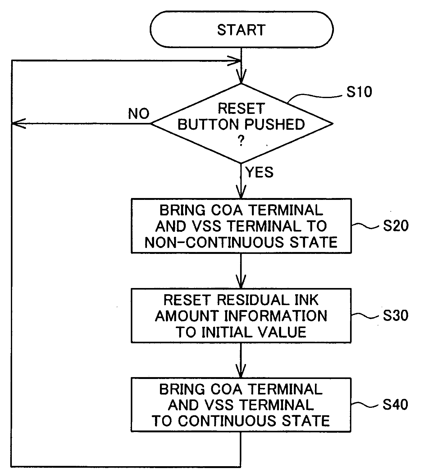
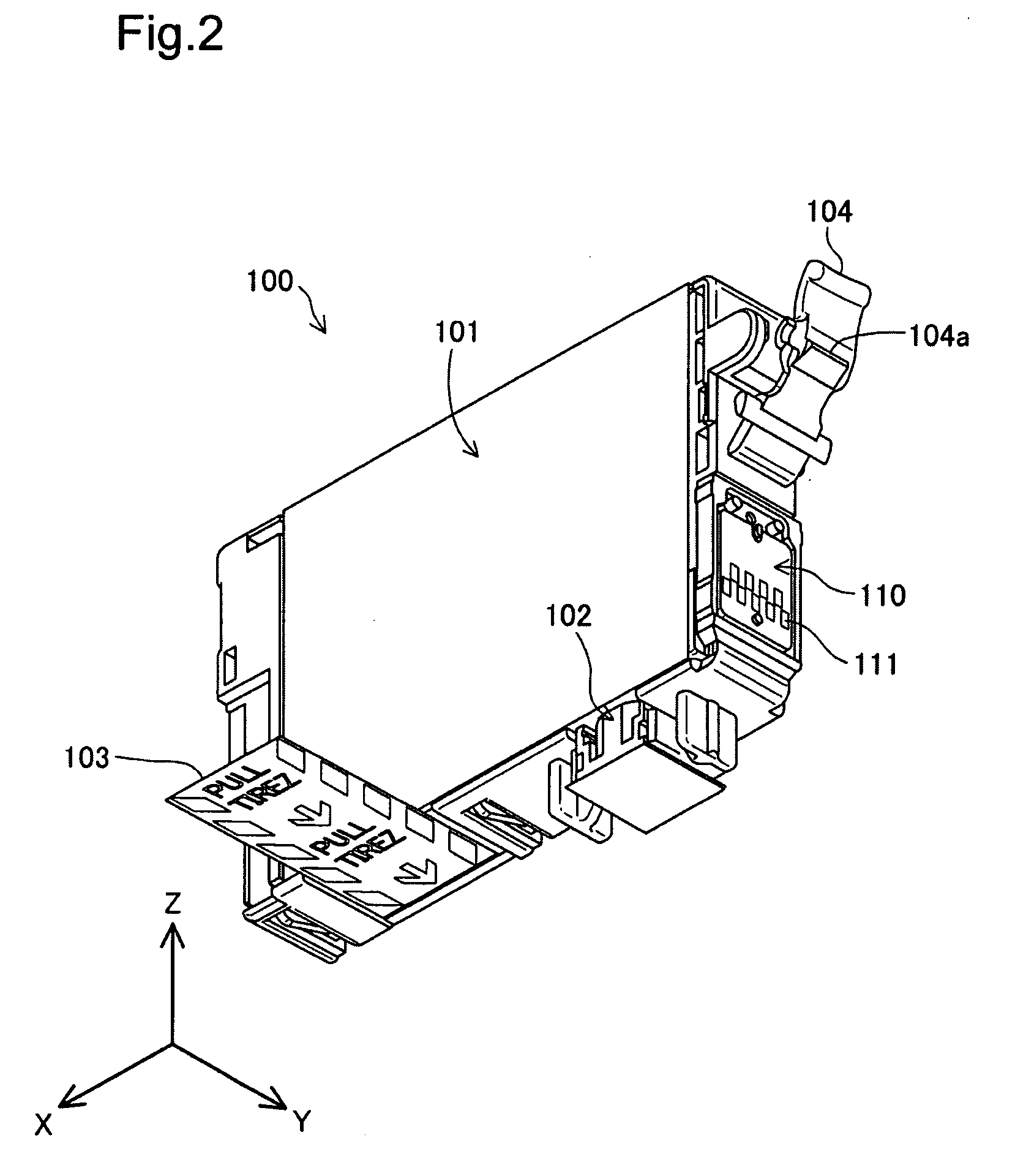
Liquid container, board, and method of rewriting liquid information
a liquid container and liquid information technology, applied in printing, other printing apparatus, etc., can solve the problems of affecting the normal operation of read/write operations to the memory, affecting the effect of data corruption, and printing will attempt to access the memory while it is being rewritten
- Summary
- Abstract
- Description
- Claims
- Application Information
AI Technical Summary
Benefits of technology
Problems solved by technology
Method used
Image
Examples
embodiment 1
A. Embodiment 1
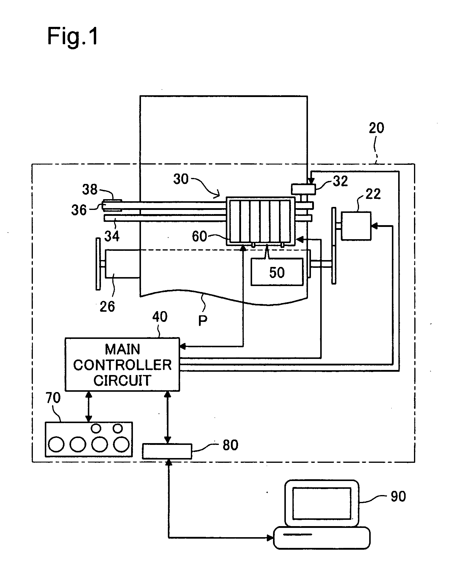
[0047]FIG. 1 is an illustration depicting a general configuration of a printing system according to an embodiment of the present invention. The printing system is furnished with a printer 20 and a computer 90. The printer 20 is connected to the computer 90 via a connector 80.
[0048]The printer 20 is furnished with a sub-scan feed mechanism, a main scan feed mechanism, a head driving mechanism, and a main controller circuit 40 for controlling these mechanisms. The sub-scan feed mechanism includes a paper feed motor 22 and a platen 26; rotation of the paper feed motor is transmitted to the platen in order to feed paper P in the sub-scanning direction. The main scan feed mechanism includes a carriage motor 32; a pulley 38; a drive belt 36 stretched between the carriage motor and the pulley; and a slide rail 34 disposed parallel to the axis of the platen 26. The slide rail 34 slidably retains a carriage 30 that is affixed to the drive belt 36. Rotation of the carriage moto...
embodiment 2
[0072]FIG. 9 is a diagram depicting an electrical configuration of an ink cartridge 100a and a printer 20 of Embodiment 2. The configuration of the printer 20 is identical to that in Embodiment 1 and will not be described here. The ink cartridge 100a of Embodiment 2 differs from that of Embodiment 1 in that it lacks a sensor 160; all nine of the terminals are instead connected to a controller 130a which is a logic circuit. The reset button 120a of the ink cartridge 100a of Embodiment 2 differs from that of Embodiment 1 in that it does not include the first switch SWa. In Embodiment 2, a sensor driving signal that the sensor access unit 53 has input via the sensor driving terminals SN, SP will be received by the controller 130a, which will always return a response signal indicating that ink 5 is present in the container body 101. Additionally, in Embodiment 2, the controller 130a is furnished with a timer function adapted to measure a prescribed time interval.
[0073]FIG. 10 is a flowc...
embodiment 3
C. Embodiment 3
[0076]FIG. 11 is a diagram depicting an electrical configuration of an ink cartridge 100b and a printer 20 of Embodiment 3. The configuration of the printer 20 is identical to that in Embodiment 1 and will not be described here. The ink cartridge 100b of Embodiment 3 differs from that of Embodiment 1 in that it lacks the reset button 120; instead, the first cartridge out terminal COA and the ground terminal VSS are connected to a controller 130b which is a logic circuit. Other arrangements are the same as in Embodiment 1.
[0077]FIG. 12 is a flowchart showing the process steps of the reset process of Embodiment 3. With the ink cartridge 100b in the installed state, the controller 130b will check the residual ink amount information periodically or each time that the residual ink amount information is updated, in order to determine whether the residual ink amount information is equal to or less than a specified value (Step S210). If the residual ink amount information exc...
PUM
 Abstract
Description
Claims
Application Information
 - R&D
- Intellectual Property
- Life Sciences
- Materials
- Tech Scout
- Unparalleled Data Quality
- Higher Quality Content
- 60% Fewer Hallucinations
Browse by: Latest US Patents, China's latest patents, Technical Efficacy Thesaurus, Application Domain, Technology Topic, Popular Technical Reports.
© 2025 PatSnap. All rights reserved.Legal|Privacy policy|Modern Slavery Act Transparency Statement|Sitemap|About US| Contact US: help@patsnap.com


