Automatic inspection device for stents, and method of automatic inspection

a technology of automatic inspection and stent, which is applied in the direction of material analysis, instruments, television systems, etc., can solve the problems of life-threatening situations, defective parts, and damage to blood cells or the blood vessels into which they are inserted

Active Publication Date: 2009-10-08
IMSTEC
View PDF3 Cites 8 Cited by
  • Summary
  • Abstract
  • Description
  • Claims
  • Application Information

AI Technical Summary

Benefits of technology

[0012]It is therefore the task of the present invention to provide a device which makes it possible to inspect both the inside and the outside surfaces of a stent quickly and automatically so that defects in its contour and surface can be detected.

Problems solved by technology

If the stent has rough or sharp edges, it can damage blood cells or the blood vessels into which they are inserted.
This can lead to further rupture of the atherosclerotic plaque, to embolisms, and to blood clots, which can lead in turn to potentially life-threatening situations.
This method, although it is highly precise, can occasionally lead to defective parts.
Accordingly, small changes in the process parameters such as the laser power, tube diameter, etc, can cause defects.
Because stents are used in the heart or in other critical areas of the circulatory system, a malfunction of the stent can be life-threatening.
Typical defects include, for example, deviations of the stent structures from the nominal dimensions and surface defects of various kinds such as contamination, scratches, sharp points, etc., which are absolutely critical to the safe functioning of the stent.
Many problems are associated with manual and automatic inspection methods.
First, human error makes the visual inspection of products less effective.
Second, manual inspection is relatively slow and thus represents a relatively expensive side of the production process.
A typical profile projector used for manual inspection, furthermore, does not usually supply numerical dimensional data, which could be important under certain conditions for process control.
This leads to reflections, which prevent automatic inspection.

Method used


Image

  • Automatic inspection device for stents, and method of automatic inspection
  • Automatic inspection device for stents, and method of automatic inspection
  • Automatic inspection device for stents, and method of automatic inspection

Examples


Embodiment Construction

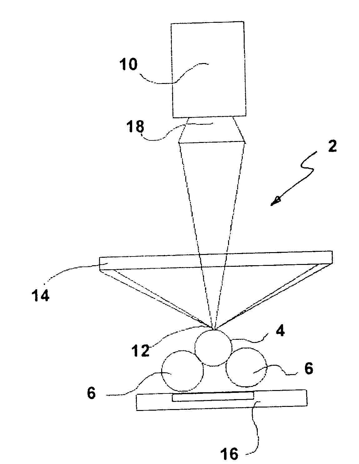
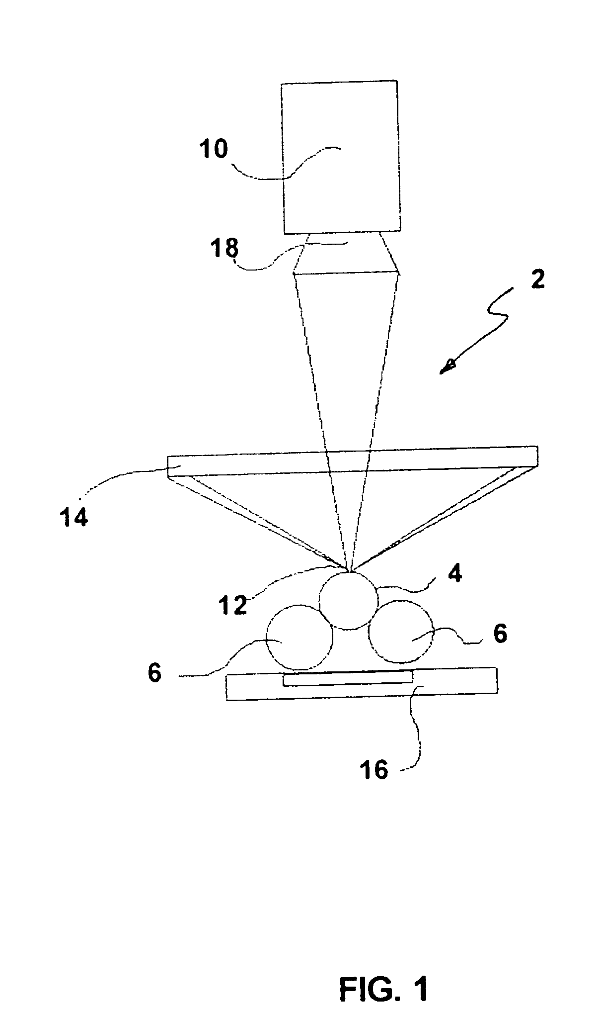
[0021]In the following, the invention is explained in greater detail on the basis of the attached drawings, which illustrate an example of the inspection of a stent. It will be obvious to the expert that the inventive device is not limited to the illumination and inspection of stents but rather can also be applied to a wide variety of tubular objects. The expert will also easily see that the inventive device can also be used to inspect both uncoated and coated samples.

[0022]As previously mentioned, cardiovascular stents are permanently placed in a blood vessel to serve as scaffolding to keep an occluded artery open. In use, stents are inserted into the artery on a catheter and typically deployed by the inflation of a very small balloon at the end of the catheter on which the stent is mounted.

[0023]As part of the process of producing stents like this, they must be carefully checked for defects. During this inspection, both the inside and the outside surface of the stent must be exami...


PUM


Abstract

A device for automatic illumination and inspection of tubular probes, in particular stents, is proposed, with rotatable means for holding the probes that are to be inspected, with an electronic camera and associated lens, with a computer-based electronic imaging system, and with means for illuminating the probe that is to be inspected. The probe surfaces are illuminated by means of a combination of dark field illumination and transillumination.

Description

FIELD OF THE INVENTION[0001]The present invention pertains generally to an automatic device for illuminating and inspecting objects such as cardiovascular stents and other small, precision-cut tubes and components.BACKGROUND OF THE INVENTIONPrior Art[0002]Stents are fine, cylindrical pieces of wire mesh, which are introduced into arteries in which deposits have formed. A balloon catheter is then used to expand the stent at the narrowed point of the artery. After the catheter is removed, the stent serves as a vascular support, which keeps the artery open. Depending on the individual situation and the area of application, stents can be designed in different ways, be of different sizes, and be made of different materials, including their coatings.[0003]Cardiovascular stents must meet stringent requirements to ensure that they will function properly. If the stent has rough or sharp edges, it can damage blood cells or the blood vessels into which they are inserted. This can lead to furth...

Claims


Application Information

Patent Timeline
Patent Type & Authority Applications(United States)
IPC IPC(8): H04N7/18G06K9/00
CPCG01B11/24G01N2021/8822G01N21/952
Inventor MAEHRINGER-KUNZ, EDGARLOEFFLER, MATTHIASRODE, REINHARDSCHNEIDER, TANJAJARSCHEL, GERALDEGGELBUSCH, KATHRIN
Owner IMSTEC
Why Eureka
Try Eureka