Method and device for synchronizing camera systems

a camera system and synchronization technology, applied in the field of automatic image processing, can solve the problems of low flexibility, unsuitable description method, and low flexibility, and achieve the effect of reducing network traffic and risk of data loss

Inactive Publication Date: 2009-10-08
BAUMER OPTRONIC
View PDF8 Cites 46 Cited by
  • Summary
  • Abstract
  • Description
  • Claims
  • Application Information

AI Technical Summary

Benefits of technology

[0019]External switching signals can each be received or transmitted by means of one or more trigger inputs or outputs of the synchronization module or modules. Switching signals output by the synchronization module can be used for triggering a camera and also for triggering a flash or, in general, a lighting device. The synchronized capture realized according to the invention with several cameras is especially advantageous in connection with lighting by one or more flashes triggered by external switching signals, because, in this way, less jitter in the propagation times via the network or, in general, minimal time differences between the captures of different cameras can be equalized.
[0022]It is especially favorable with respect to no-delay or at least small-delay control of the cameras when the synchronization module and camera have two logical channels that have different priorities for each data direction.
[0029]According to another refinement of the invention, one or more cameras could be designed in order to transmit the readiness for a new image capture or the end of the image data transmission to a synchronization module via the network, advantageously as a real-time-critical control signal. Referring to this signal, the synchronization module can recognize that a delay-free image capture is now possible, without having to interrupt the transmission of image data by the camera. This embodiment of the invention is especially favorable when simultaneous image capture is the priority and the absolute time of the image capture is less of a priority.
[0030]Furthermore, it can be favorable if the synchronization module is formed to transmit to a camera a signal for interrupting an image transmission and / or another signal for repeating the transmission of a part of an interrupted image from the image memory of this camera. A separate signal for interrupting the image transmission can then be transmitted shortly before the transmission of a trigger signal or an image-capture signal via the first logical channel. This reduces the network traffic during the transmission of the image-capture signal, and thus also the risk of data loss.

Problems solved by technology

The described method is unsuitable, however, for fast response times.
The disadvantage of these solutions is the low flexibility, because one transmission channel is constantly busy.
This, however, requires a previously known behavior of the bus subscribers.

Method used


Image

  • Method and device for synchronizing camera systems
  • Method and device for synchronizing camera systems
  • Method and device for synchronizing camera systems

Examples


embodiment 1

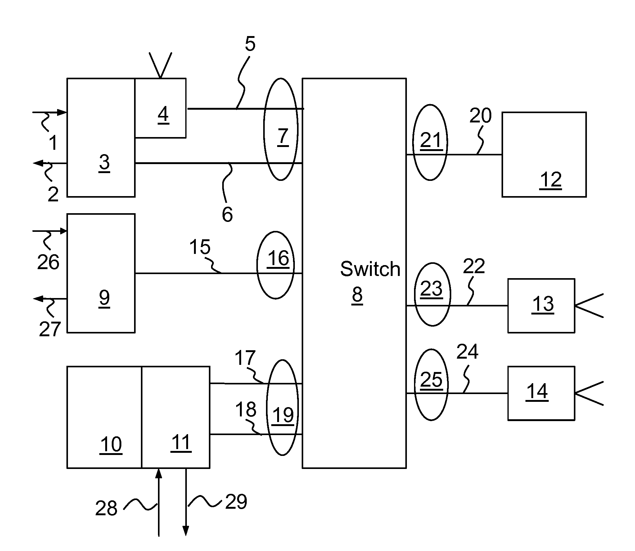
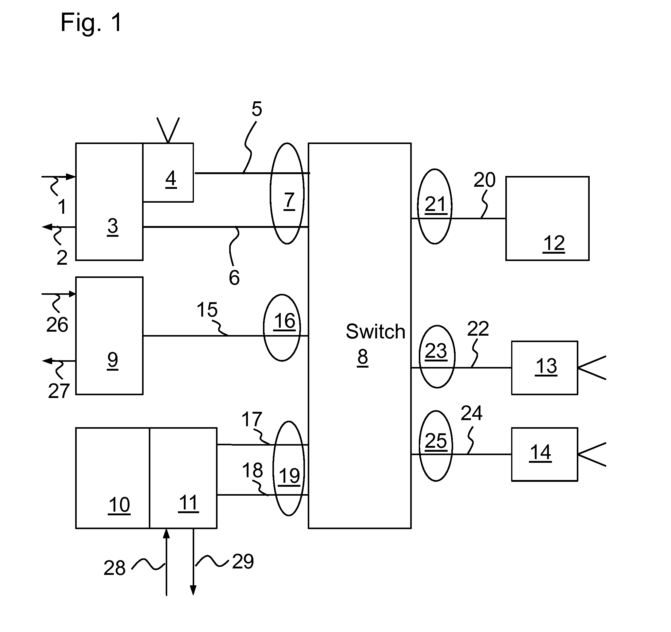
[0040]FIG. 1 shows, as an example, a typical realization of a camera network. Below, designations that are typical for Ethernet have been selected. However, it is clear to someone skilled in the art that the embodiment can be applied accordingly to other duplex-capable networks (IEEE1394, etc.).

Switches and Hubs

[0041]An Ethernet hub is a non-intelligent multiport repeater for connecting Ethernet devices. Hubs are very fast since the packets are neither stored nor relayed. With a hub, one speaks of a “shared” Ethernet, i.e., exactly one device can transmit at a single point in time; all of the other devices must wait during this time. The propagation times are no longer predictable, even for networks with low loads. For this reason, hubs are not preferred for networking the network components to each other.

[0042]Therefore, at the least, switching hubs (switches) are preferred. A switch examines each Ethernet frame with respect to its embedded target address and selectively relays the...

embodiment 2

[0061]FIG. 4 shows a system in which synchronization modules are used with memories that store the propagation times between different synchronization modules (38 . . . 40). With the knowledge of these propagation times, path-dependent delay information can be transmitted along with the trigger command.

[0062]In FIG. 4, the reference numeral 8 refers to a switch; each of 9, 30, and 34 refers to a synchronization module formed, in particular, as a stand-alone unit; 12 refers to an image-processing device, for example, a PC; 13 and 14 each refer to a camera unit formed as a stand-alone unit; 16, 21, 23, 25, 32, 35, and 36 refer to physical Ethernet connections or Ethernet network cables; 26 and 31 refer to trigger inputs; 37 refers to a signal output, for example, for triggering a flash; 38 refers to a delay A; 39 refers to a delay B; and 40 refers to a delay C. In the sense of the invention, a stand-alone unit is understood to be a unit that is directly coupled to the network.

embodiment 3

[0063]In FIG. 5, the reference numeral 54 refers to an image-processing device, for example, a PC; 55 and 56 each refer to a switch; 57, 58, 59, 60, 61, 62, 63, 64 refer to physical Ethernet connections or Ethernet network cables; 65, 66, 67, and 68 refer to networks connected to the switches 33 or 35; 69 refers to a logical path with a delay A and a jitter A; and 70 refers to a logical path with a delay B and a jitter B.

[0064]In FIG. 5, a network is shown in which the delay times and the jitter between the network components are known (e.g., delay and jitter between switch (8) and switch (33)) and are stored in matrix form in the synchronization modules 9, 30, 34. The corresponding times for an end-to-end connection (e.g., path (69) composed of the sections (9.8), (8.33), (33.65), (56.13)) can be calculated from the sum of the times of the sections. If two paths are possible for an end-to-end connection, the path that is best-suited for the application can be selected with referenc...


PUM


Abstract

The invention relates to a method and to a device for synchronizing the image capture by cameras. For this purpose, a duplex-capable network is provided. Within the network, one or more hardware-supported synchronization modules with a logical channel of a first type are provided, wherein the synchronization module or modules transmit, via the logical channel, image-capture signals that control the capture time of image sensors, wherein the image-capture signals are received by image-capture devices, and wherein the image-capture devices each capture an image as a response to the reception of an image-capture signal, and wherein the image data is then transmitted via the network by the image-capture devices via a logical channel of a second type.

Description

FIELD OF INVENTION[0001]The present invention relates to the field of automatic image processing in general and, more particularly, to synchronizing camera systems.BACKGROUND OF THE INVENTION[0002]For automatic image processing, the networking of cameras, peripheral sensors, and computers into complex systems is playing an increasingly important role. Communications are performed via standardized networks, the most well-known of which are Firewire IEEE 1394 and Ethernet IEEE802.3. For connecting cameras, other standards are available, the most well-known are of which DCAM and the GigE-Vision™ standard published by AIA (Automated Imaging Association).[0003]In addition to providing high bandwidth for the transmission of images, precise time synchronization of cameras, lighting units, and other sensors is a basic prerequisite for high performance.[0004]In EP1793574, a communications method that can be used in the field of telecommunications is described as an example in which, by means...

Claims


Application Information

Patent Timeline
Patent Type & Authority Applications(United States)
IPC IPC(8): H04N5/06H04L5/14H04N5/232
CPCH04N5/0733H04N5/232H04N21/4305H04N7/181H04N21/242H04N5/23206H04N23/662
Inventor IHLEFELD, JOACHIMKUNZE, CARSTENOELSCHLAEGER, THOMASRAEDISCH, FRANKSCHARF, DIETMARVIETZE, OLIVER
Owner BAUMER OPTRONIC
Why Eureka
Try Eureka