Optical rotary adapter and optical tomographic imaging system using the same

a technology of optical tomography and rotary adapter, which is applied in the field of optical rotary adapter and optical tomographic imaging system, can solve problems such as unaddressed problems, and achieve the effect of reducing the signal-to-noise ratio and efficient acquisition

Active Publication Date: 2009-10-08
TERUMO KK
View PDF8 Cites 49 Cited by
  • Summary
  • Abstract
  • Description
  • Claims
  • Application Information

AI Technical Summary

Benefits of technology

[0030]According to the first aspect of the invention directed to the optical rotary adapter, the optical fibers guiding the measuring light to the object under measurement and guiding the returning light from the object under measurement are rotatably and, preferably, detachably connected, the connecting ends of the optical fibers can be protected from break or damage when attaching or detaching the optical fibers, and the attenuation of the returning light from the object under measurement and the decrease of the signal-to-noise ratio thereof occurring at the opposite ends of the connected optical fibers as light is reflected at the end faces can be prevented.
[0031]A second aspect of the invention directed to the optical tomographic imaging system achieves efficient acquisition of a high-resolution tomographic image of the object under measurement by using the optical rotary adapter according to the first aspect capable of producing said effect.

Problems solved by technology

However, such a problem was not addressed in the optical rotary joint disclosed in JP 2000-131222 A in any manner.

Method used


Image

  • Optical rotary adapter and optical tomographic imaging system using the same
  • Optical rotary adapter and optical tomographic imaging system using the same
  • Optical rotary adapter and optical tomographic imaging system using the same

Examples


Embodiment Construction

[0041]Now, the inventive optical rotary adapter and the optical tomographic imaging system using the same will be described in detail referring to the embodiments illustrated in the attached drawings.

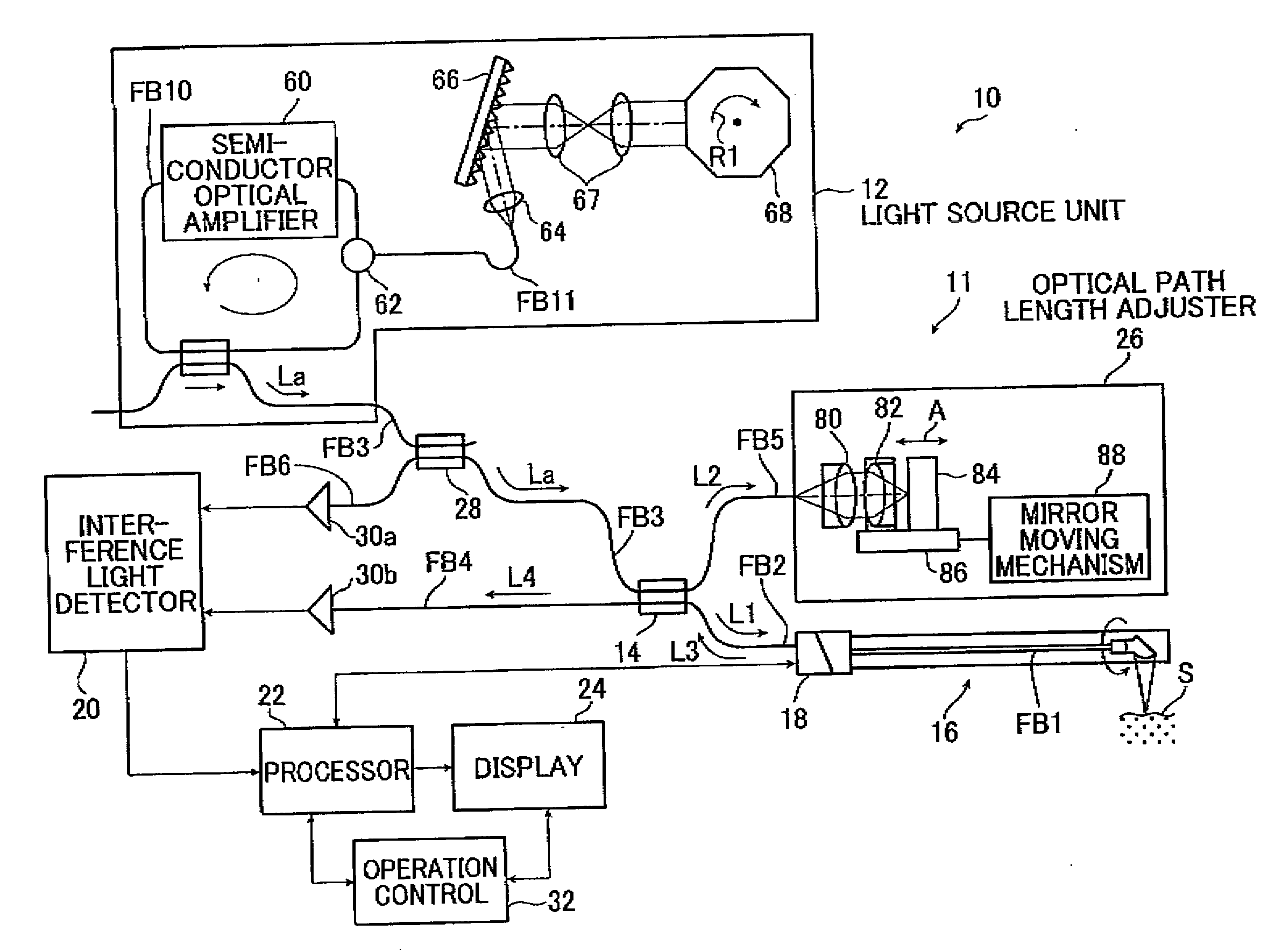
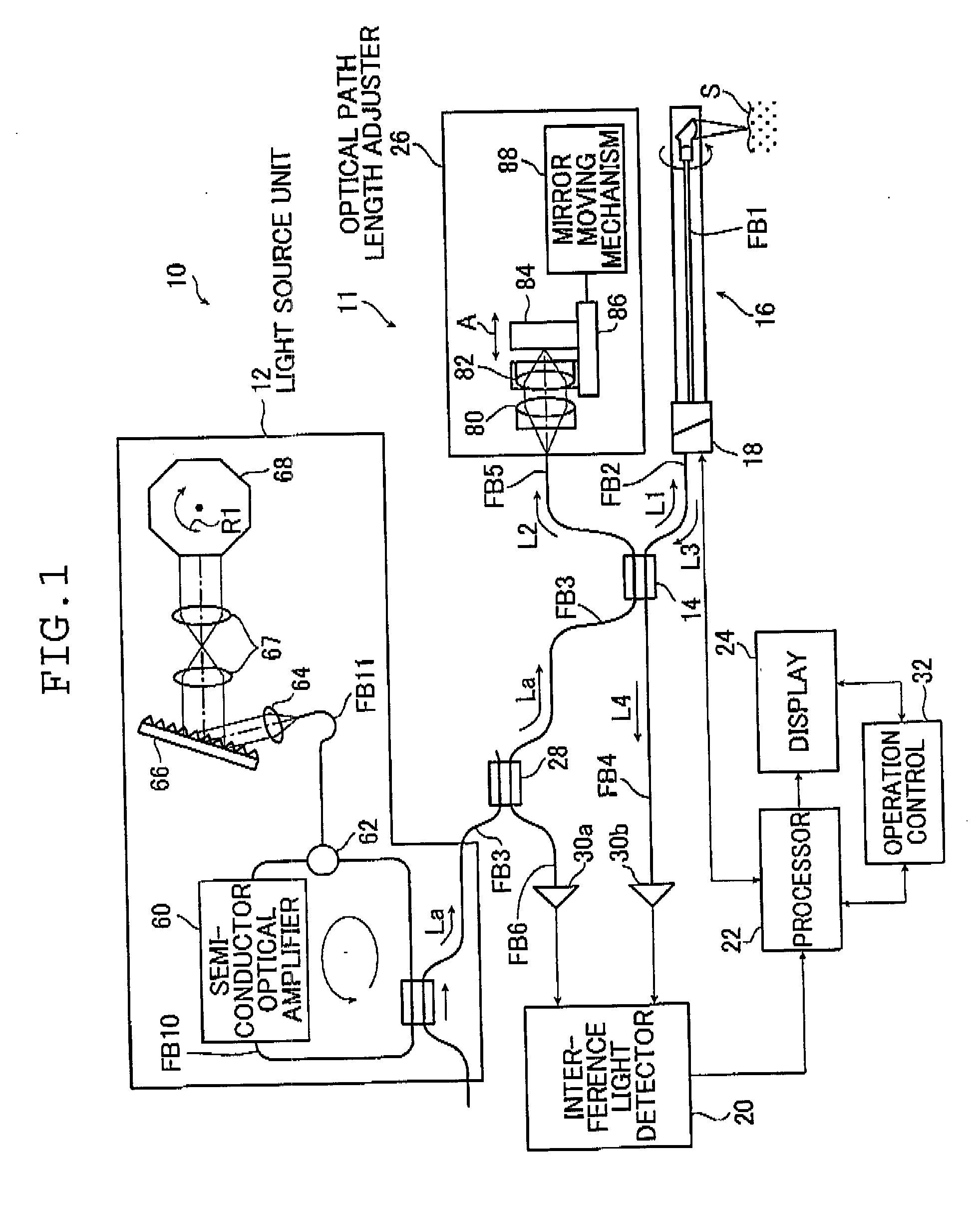
[0042]FIG. 1 is a block diagram illustrating a schematic configuration of an embodiment of the inventive optical tomographic imaging system using the inventive optical rotary adapter.

[0043]An optical tomographic imaging system 10 according to the invention illustrated in FIG. 1 acquires a tomographic image of an object under measurement by a measuring method based upon optical coherence tomography or OCT. The optical tomographic imaging system 10 comprises:

[0044]a main body of the system 11 including[0045]a light source unit 12 for emitting light La,[0046]a splitter / combiner 14 for splitting the light La emitted by the light source unit 12 into measuring light L1 and reference light L2 and combining returning light L3 from the object under measurement or the sample under test and the re...


PUM


Abstract

The optical rotary adapter is used with an optical tomographic imaging system for acquiring an optical tomographic image of an object under measurement. The adapter includes a fixed sleeve, a stationary optical fiber supported by the fixed sleeve and having an inclined end face, a stationary collimating lens spaced a given distance from the inclined end face, a mounting cylinder carried rotatably with respect to the fixed sleeve, a rotary optical fiber mounted to the mounting cylinder and having an inclined end face, a rotary collimating lens mounted to the mounting cylinder and disposed with a given distance from the inclined end face, and a rotation actuating device for rotating said mounting cylinder. The central axes of the stationary and rotary optical fibers are offset from or inclined with respect to a central axis of rotation of the mounting cylinder to reduce attenuation of returning light from the object.

Description

[0001]The entire contents of the literature cited in this specification are incorporated herein by reference.BACKGROUND OF THE INVENTION[0002]The present invention relates to an optical rotary adapter and an optical tomographic imaging system using the same and more specifically to an optical rotary adapter that provides rotatable connection between optical fibers for guiding measuring light to the object under measurement and guiding returning light from the object under measurement to acquire an optical tomographic image of the object under measurement and an optical tomographic imaging system that irradiates the object under measurement with light and acquires a tomographic image from the light reflected by and returned from the object under measurement.[0003]Acquisition of a cross-sectional image of a sample under measurement such as biological tissue without cutting thereinto may be achieved using an optical tomographic imaging system employing optical coherence tomography (OCT...

Claims


Application Information

Patent Timeline
Patent Type & Authority Applications(United States)
IPC IPC(8): G01B9/02G02B6/26
CPCA61B5/0066A61B5/0073G01N21/4795G01N2021/1787G02B6/327G02B6/3604G01B9/02083G01B9/02004G01B9/0205G01B9/02091G01B9/02061G01B2290/70H04B10/225H04B10/25
Inventor MASUDA, TADASHI
Owner TERUMO KK
Why Eureka
Try Eureka