Expansion Dowel

a dowel and expansion technology, applied in the field of expansion dowels, can solve the problems of loosening of the dowel parts from each other, and achieve the effect of convenient mounting

Inactive Publication Date: 2009-10-08
HILTI AG
View PDF12 Cites 11 Cited by
  • Summary
  • Abstract
  • Description
  • Claims
  • Application Information

AI Technical Summary

Benefits of technology

[0017]Advantageously, in one of the dowel parts, there are provided, on its rim, which is bringable in abutment with the another of the dowel parts, at least one overlapping section projecting past the rim in an axial direction and axially overlapping, in an assembled condition of the dowel body, at least one axial region of the another of the dowel parts. This ensures a simple easy form of the snap connection device that, advantageously, is provided in the region of the overlapping section in the assembled condition of the dowel body. The wall thickness of the overlapping section is advantageously, smaller than the wall thickness in any other region of the corresponding dowel part. Therefore, the overlapping section easily expands upon assembly of the dowel parts until the engagement element engages in the receiving element of the snap connection device.
[0018]Advantageously, at least one locking element is provided on the at least one overlapping section and which engages, in the assembled condition of the dowel body, at least one counter-locking element provided on the another of the dowel parts. The locking connection ensures that the overlapping section is reliably retained, in the assembled condition of the dowel body, on another dowel part, and does not expand outwardly or inwardly during mounting of the expansion dowel. This ensures an easy mounting, without any hindrance, with one extending overlapping section.

Problems solved by technology

The drawback of the dowel disclosed in the above-discussed German Publication consists in that during assembly, in particular, of two dowel parts, the dowel parts can become loose from each other before insertion or during the insertion of the expansion member, and specifically, before the expansion member expands the expansion region for an adequate anchoring of the dowel in a constructional component.

Method used


Image

  • Expansion Dowel
  • Expansion Dowel
  • Expansion Dowel

Examples


Embodiment Construction

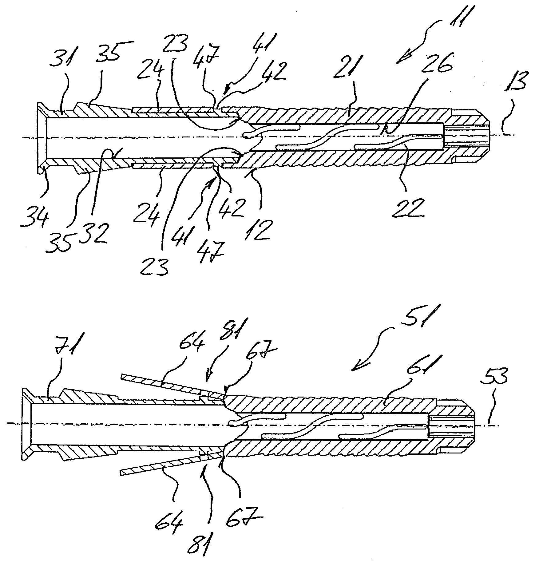
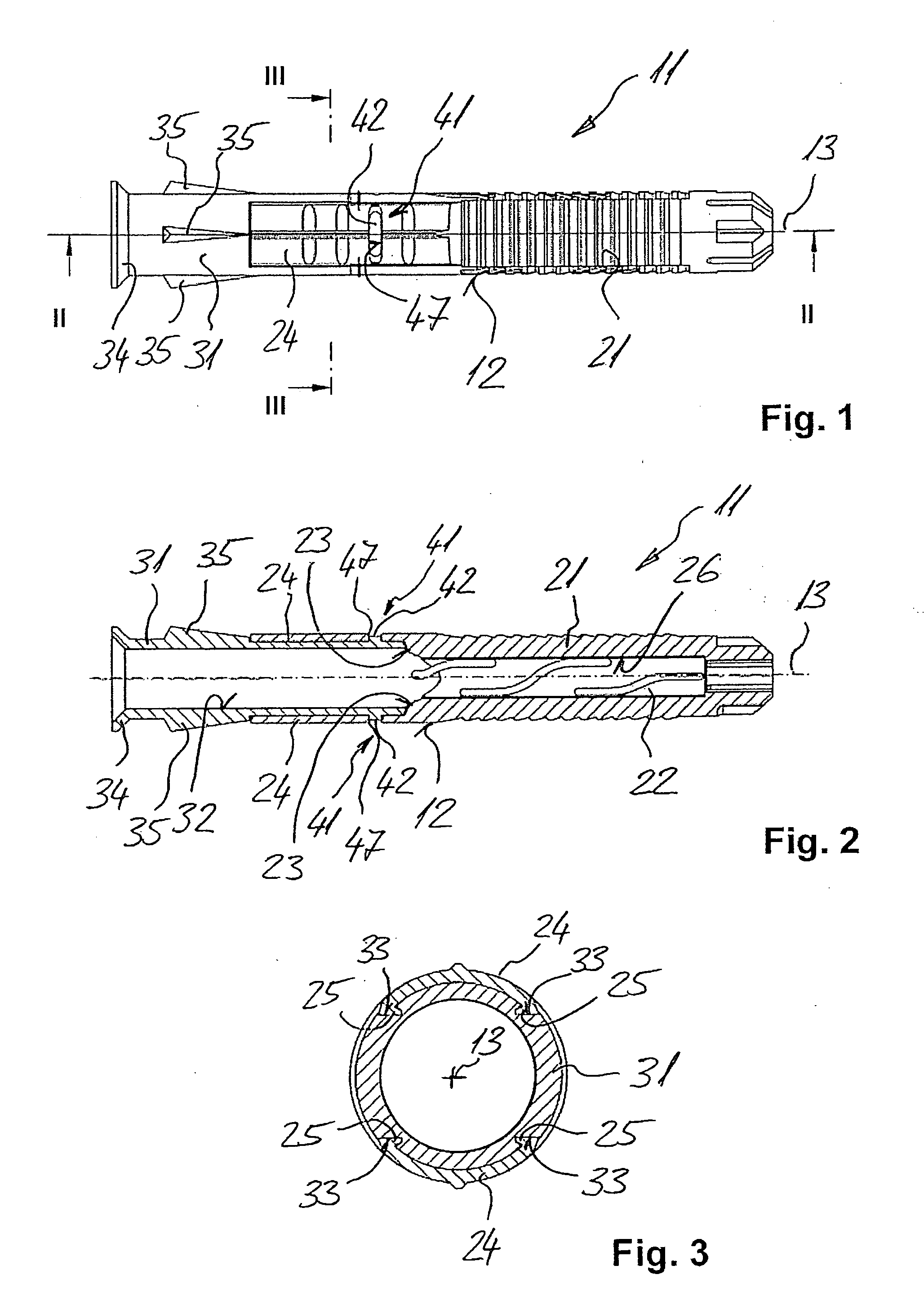
[0028]An expansion dowel 11 according to the present invention, which is shown in FIGS. 1-3, has a sleeve-shaped dowel body 12 extending along a dowel longitudinal axes 13 and having a first, front, in the setting direction, dowel part 21 with an expansion region 22, and a second dowel part 31 having a stem region 32 and axially adjoining the first dowel part 21. An expansion member, not shown, such as, e.g., an expansion screw or an expansion pin is extendable through both dowel parts 21 and 31. The two dowel parts 21 and 31 are connectable with a snap connection device 41. The first dowel part 21, which is provided with the expansion region 22, is formed of a high-grade plastic material, such as, e.g., polyamide (PA). The second dowel part 31 with a stem region 32 is formed of a plastic material having a not so high grade, such as, e.g., polyethylene (PE) or polypropylene (PP).

[0029]On the first dowel part 21, there are provided, on a rim 23 that can be brought in abutment with th...


PUM


Abstract

An expansion dowel includes a sleeve-shaped dowel body (12) having a first dowel part (21; 61) and at least one second dowel part (31; 71) axially adjoining the first dowel part (21; 61), and at least one snap connection device (41; 81) for connecting the first (21; 61) and second (31; 71) dowel parts together and having an engagement element (42) provided on one of the first and second dowel parts (31; 71) and a receiving element (47) for the engagement element (42) and provided on another of the first and second dowel parts (21; 61).

Description

BACKGROUND OF THE INVENTION[0001]1. Field of the Invention[0002]The present invention relates to an expansion dowel including a sleeve-shaped dowel body having a first dowel part and at least one second dowel part axially adjoining the first dowel part and through which an expansion member is extandable; and at least one connection device for connecting the two dowel parts together.[0003]2. Description of the Prior Art[0004]For connecting different parts to constructional elements such as, e.g., walls and ceilings, an expansion dowel of the type discussed above is inserted, e.g., during through-assembly, through an opening in the to-be connected parts and into a preliminary formed bore in the constructional element. The expansion dowel is expanded with an expansion member such as, e.g., an expansion screw, in the preliminary formed bore in the constructional element in order to be anchored there. The dowel body has, at its setting direction end, a radially expandable region and a st...

Claims


Application Information

Patent Timeline
Patent Type & Authority Applications(United States)
IPC IPC(8): F16B13/04
CPCF16B13/126F16B13/124
Inventor ZIMMERER, CLAUDIAPOPP, FRANZDAIGELER, ERICH
Owner HILTI AG
Why Eureka
Try Eureka