Eureka AIR delivers breakthrough ideas for toughest innovation challenges, trusted by R&D personnel around the world.

Temperature setting method of heat processing plate, temperature setting apparatus of heat processing plate, program, and computer-readable recording medium recording program thereon

a technology of temperature setting apparatus and heat processing plate, which is applied in the direction of hot plate heating arrangement, preheating charge, special data processing application, etc., can solve the problem that the temperature within the wafer to be processed did not become precisely uniform in the actual processing period, and achieve the effect of improving yield

Active Publication Date: 2009-10-08
TOKYO ELECTRON LTD
View PDF17 Cites 28 Cited by
  • Summary
  • Abstract
  • Description
  • Claims
  • Application Information

AI Technical Summary

Benefits of technology

[0033]According to the present invention, the substrate can be precisely uniformly heat-processed in an actual heat processing time, so that the processing within the substrate is uniformly performed, resulting in improved yields.

Problems solved by technology

However, when the temperature setting of the heating plate was performed at the point in time when the in-plane temperature of the temperature measuring wafer became uniform after the temperature measuring wafer was mounted on the heating plate and kept standing for about 10 minutes to about 20 minutes as described above, actually it was verified that the temperature within a wafer to be processed did not become precisely uniform in an actual wafer processing period which is finished in about 60 seconds to about 90 seconds after the wafer is mounted on the heating plate.

Method used


Image

  • Temperature setting method of heat processing plate, temperature setting apparatus of heat processing plate, program, and computer-readable recording medium recording program thereon
  • Temperature setting method of heat processing plate, temperature setting apparatus of heat processing plate, program, and computer-readable recording medium recording program thereon
  • Temperature setting method of heat processing plate, temperature setting apparatus of heat processing plate, program, and computer-readable recording medium recording program thereon

Examples


Embodiment Construction

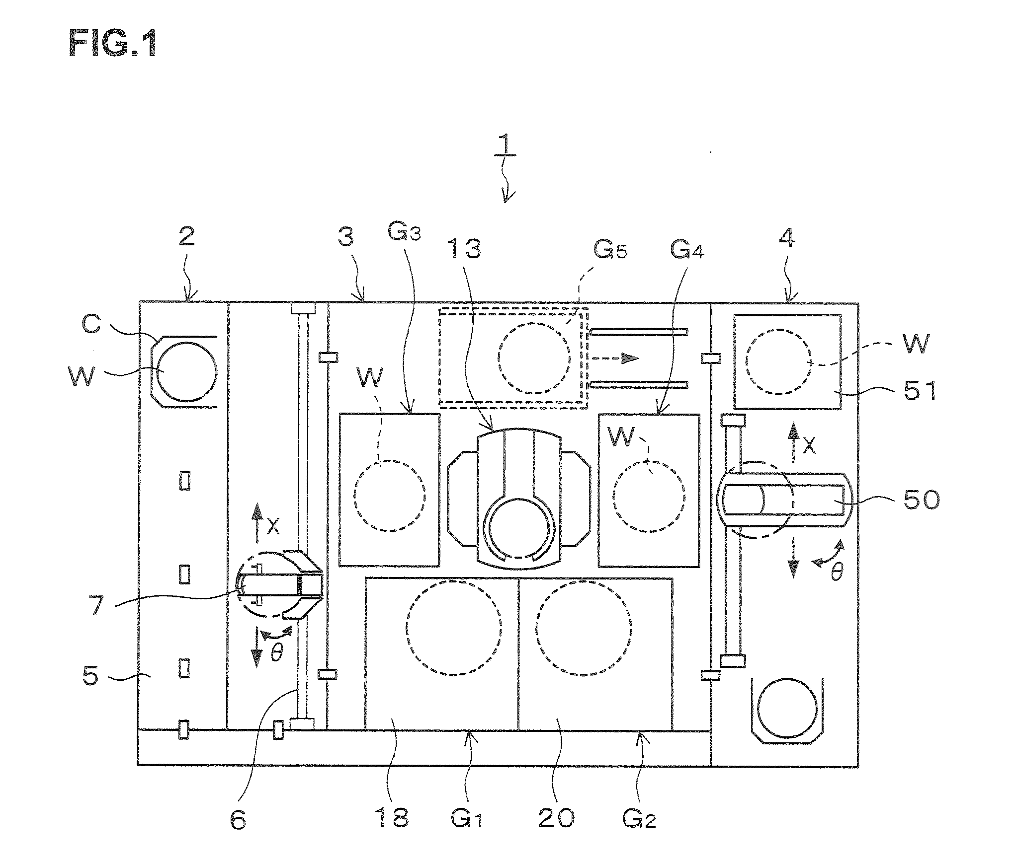
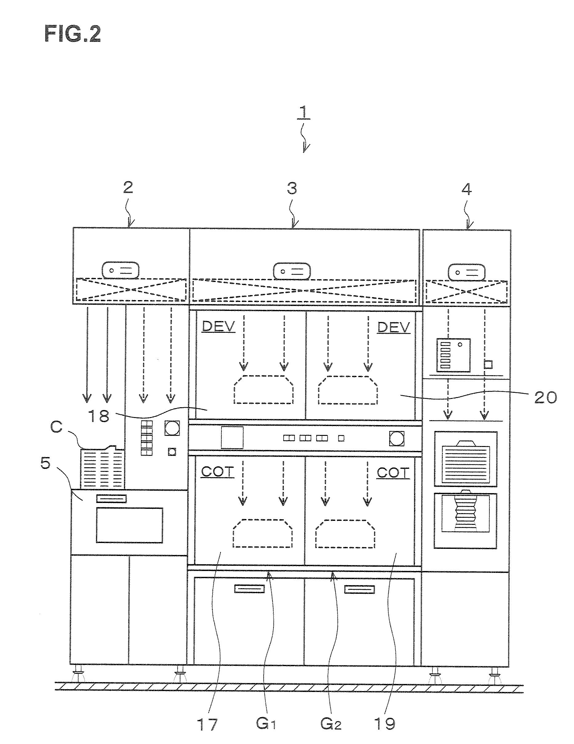
[0076]Hereinafter, a preferred embodiment of the present invention will be described. FIG. 1 is a plan view showing the outline of a configuration of a coating and developing treatment system 1 in this embodiment, FIG. 2 is a front view of the coating and developing treatment system 1, and FIG. 3 is a rear view of the coating and developing treatment system 1.

[0077]The coating and developing treatment system 1 has, as shown in FIG. 1, a configuration in which, for example, a cassette station 2 for transferring, for example, 25 wafers W per cassette as a unit from / to the outside into / from the coating and developing treatment system 1 and transferring the wafers W into / out of a cassette C; a processing station 3 including a plurality of various kinds of processing and treatment units, which are multi-tiered, for performing predetermined processing or treatment in a manner of single wafer processing in the photolithography process; and an interface section 4 for delivering the wafers W...


PUM


Abstract

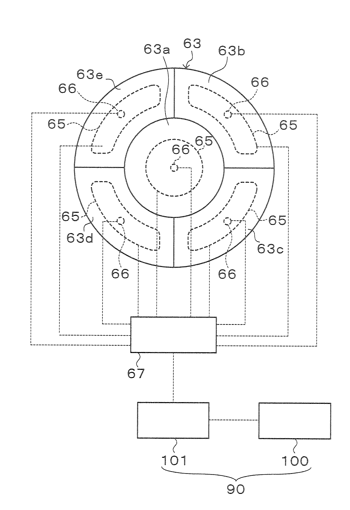
An object of the present invention is to perform temperature setting of a heating plate so that a wafer is uniformly heated in an actual heat processing time. The temperature of a wafer is measured during a heat processing period from immediately after a temperature measuring wafer is mounted on the heating plate to the time when the actual heat processing time elapses. Whether the uniformity in temperature within the wafer is allowable or not is determined from the temperature of the wafer in the heat processing period, and if the determination result is negative, a correction value for a temperature setting parameter of the heating plate is calculated using a correction value calculation model from the measurement result, and the temperature setting parameter is changed.

Description

TECHNICAL FIELD [0001]The present invention relates to a temperature setting method of a heat processing plate, a temperature setting apparatus of a heat processing plate, a program, and a computer-readable recording medium recording the program thereon.BACKGROUND ART [0002]In a photolithography process in manufacturing, for example, a semiconductor device, for example, a plurality of kinds of heat processing such as heat processing of evaporating a solvent in a resist film applied on a wafer (pre-baking), heat processing of accelerating the chemical reaction in the resist film after exposure of a pattern post-exposure baking), and heat processing after developing treatment (post-baking) and so on are performed[0003]The above heat processing is usually performed in a heat processing unit by mounting and heating the wafer on a heating plate. To manufacture semiconductor devices uniform within the wafer, it is necessary to heat the wafer at a temperature uniform within the wafer. To t...

Claims


Application Information

Patent Timeline
IPC IPC(8): G05D23/19F24J3/00
CPCH01L21/67103H01L21/67248H01L21/67178
Inventor IWANAGA, SHUJISATA, NOBUYUKI
Owner TOKYO ELECTRON LTD
Why Eureka
Eureka Blog
Learn More