Protective covering

a protective covering and protective technology, applied in the field of protective coverings, can solve the problems of many existing protective paddings or devices not adequately protecting objects from pain, injury or damage, and may become displaced from its original or optimal position, and achieve the effect of superior impact resistan

Inactive Publication Date: 2009-10-15
WARRIOR SPORTS INC
View PDF32 Cites 27 Cited by
  • Summary
  • Abstract
  • Description
  • Claims
  • Application Information

AI Technical Summary

Benefits of technology

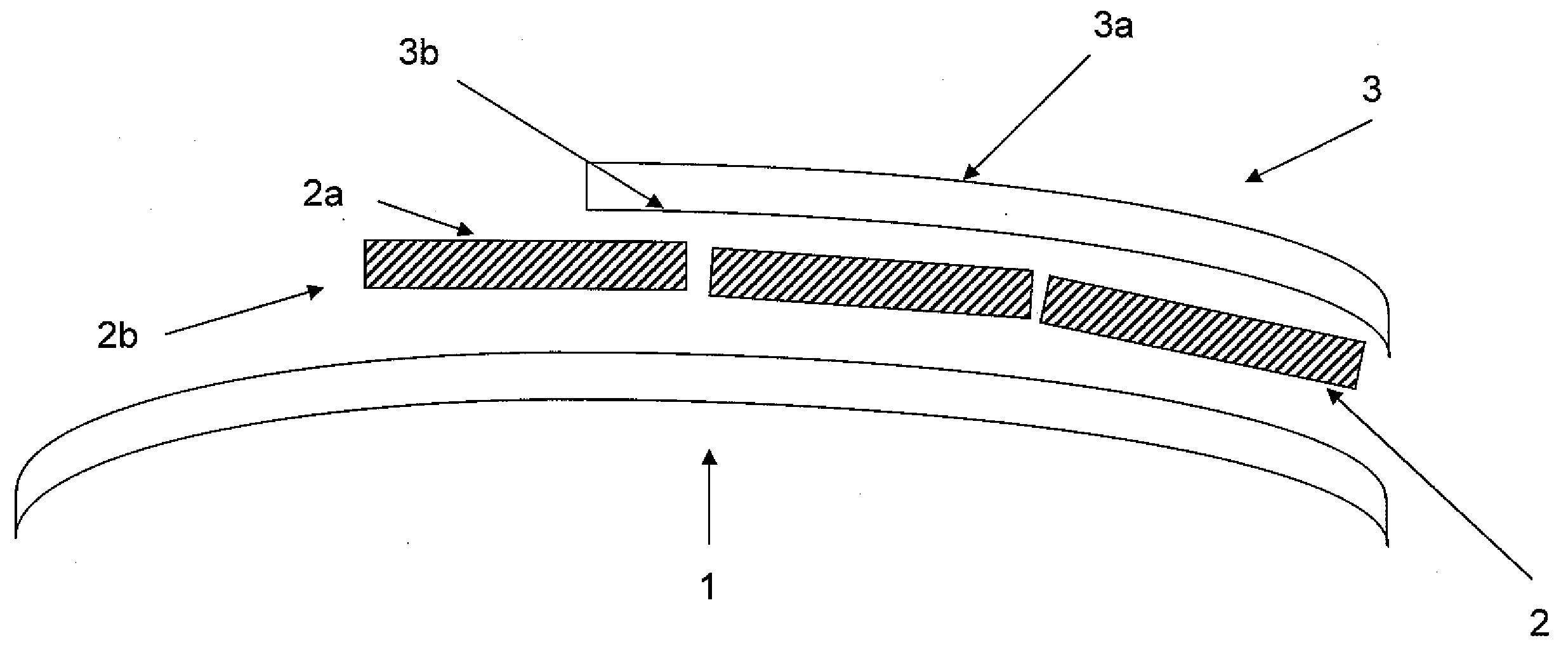
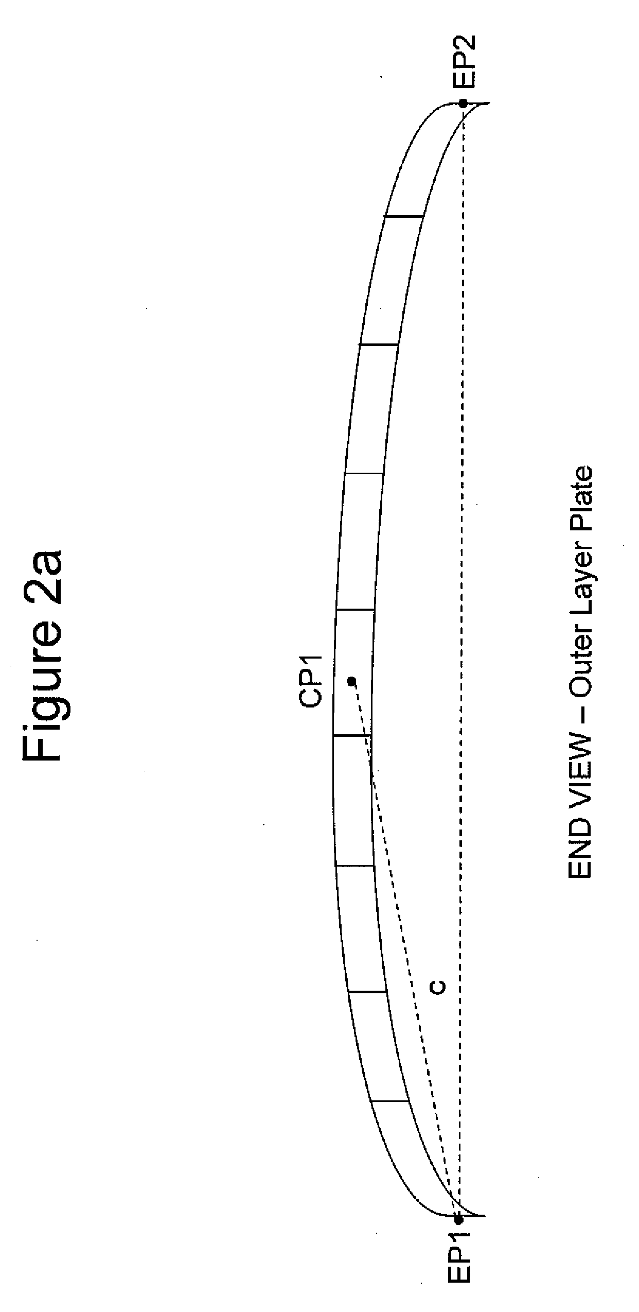
[0006]The present invention is directed to a protective covering that is shaped to fit a contoured or moving object and provide superior impact resistance. The protective covering of the present invention comprises at least one outer layer having a plurality of outer layer plates shaped to the contours or anticipated movement of an object to be protected. The outer layer plates are made of a substantially rigid, shape-retaining material. The protective covering also comprises at least one inner layer having a plurality of inner layer units made from impact absorbing materials.

Problems solved by technology

Sports activities such as baseball, basketball, football, ice hockey, field hockey, soccer, on-road and off-road biking, roller blading, roller skating, skateboarding, snow skiing, snowboarding, boogie boarding, surfing, and windsurfing have revealed that falls, collisions and impacts can result and cause pain, injury and damage to unprotected parts of the body.
Nevertheless, many existing protective paddings or devices do not adequately protect objects from pain, injury or damage resulting from impacts.
However, protective padding may become displaced from its original or optimal position when an object is contoured or in motion.
During activity, these devices can shift due to either improper fit, discomfort of the user or simple movement.
Displaced padding does not provide optimal protection for objects from damage or otherwise experiencing an impact from forces being applied to them.

Method used


Image

  • Protective covering
  • Protective covering
  • Protective covering

Examples


example 1

A Shin Pad

[0063]A protective covering for a shin was manufactured from a plastic shin cover using a commercially available shin pad and a layer of padding. The padding layer comprised a plurality of soft padding units. The plastic shin cover was cut into hexagonal pieces approximately 2 cm in diameter. The pieces were placed on the padding in essentially the same way the pieces were aligned in the original, uncut shin pad prior to cutting. The pieces were connected to the padding by a thermoplastic fiber. A fiber was passed through the center of a piece and through the padding and tied off at each end. Finally, the excess padding was removed. Representative shin pads are shown in FIGS. 3 and 6.

example 2

A Sports Bra

[0064]A protective covering for a sports bra was manufactured from a hard shell plastic mold of a female body and a layer of padding. The padding layer comprised a plurality of soft padding units. The plastic mold was cut into hexagonal pieces approximately 2 cm in diameter. The pieces were placed on the padding in essentially the same way the pieces were aligned in the original, uncut mold prior to cutting. The pieces were connected to the padding by a hot melt adhesive. The excess padding was removed. The protective covering was connected to a fabric in the shape of a sports bra.

example 3

A Soccer Football Shin Pad

[0065]Protective coverings for a shin were manufactured by over-molding 32 separate geometric outer tiles onto a mesh polyester fabric in a way that resulted in a permanent bond. Polypropylene plastic was over-molded (e.g. insert-molding) by injected onto 350G polyester fabric forming outer tiles with a maximum thickness of 2.8 mm. The padding layer comprised a uniform reticulated EVA (ethylene vinyl acetate) foam heat embossed into the form of a plurality of soft padding units. These two components were attached to each other by sewing the perimeters together. An optional intermediate layer was used. The intermediate layer was placed in-between the outer layer plate and the inner layer. The intermediate layer comprised either EVA foam or polyethylene plastic, each having an elongated trapezoid shape about 7 cm wide at the top, about 5 cm wide at the bottom, about 16 cm tall, and about a 0.6 cm thickness. Finally, the excess padding was removed. Representat...


PUM

PropertyMeasurementUnit
forceaaaaaaaaaa
displacementaaaaaaaaaa
thicknessaaaaaaaaaa

Abstract

The present invention provides a protective covering with a hard outer layer and a soft inner layer. The hard outer layer comprises a plurality of substantially rigid shape-retaining and interworking tiles anatomically conformed to a contoured object. The outer layer has sufficient flexibility to adjust its conformity to the object as the object's contour changes. The soft inner layer comprises a plurality of impact absorbing units. The protective covering provides impact resistance and is designed to remain securely in place and protective of the object even when the contour of the object changes.

Description

CROSS REFERENCE TO RELATED APPLICATIONS[0001]This application claims the benefit of U.S. Provisional Application No. 61 / 028,741 filed Feb. 14, 2008 and U.S. Provisional Application No. 61 / 111,839, filed Nov. 6, 2008, the contents of both of which are incorporated herein by reference.FIELD OF THE INVENTION[0002]The present invention relates to a protective covering suitable for impact resistance with at least one hard outer layer and at least one soft inner layer. The hard outer layer comprises a plurality of substantially rigid shape-retaining plates anatomically conformed to a contoured object. The outer layer comprises sufficient flexibility to adjust its conformity to the object as the object's shape changes. The soft inner layer comprises a plurality of impact absorbing units. The protective covering is designed to provide impact resistance and to remain securely in place to provide such protection even when the contour of the object changes.BACKGROUND OF THE INVENTION[0003]Prot...

Claims


Application Information

Patent Timeline
Patent Type & Authority Applications(United States)
IPC IPC(8): A41D13/00A41D13/015B32B3/16B32B7/022
CPCB32B3/16Y10T428/16Y10T428/164F41H5/0492B32B5/022B32B5/024B32B5/06B32B5/245B32B5/32B32B7/12B32B9/005B32B9/045B32B9/046B32B9/047B32B15/046B32B15/085B32B15/14B32B27/065B32B27/08B32B27/12B32B27/32B32B27/34B32B1/00B32B3/08B32B3/14B32B2262/0261B32B2262/0276B32B2262/0292B32B2266/0221B32B2266/04B32B2307/546B32B2307/558B32B2439/00B32B2571/00B32B7/022
Inventor SANDUSKY, DONALD ALLANALTENBURGER, RYAN
Owner WARRIOR SPORTS INC
Why Eureka
Try Eureka