
Dynamic balancing apparatus and method using simple harmonic angular motion

a dynamic balancing and harmonic angular motion technology, applied in the direction of measuring devices, instruments, structural/machine measurement, etc., can solve the problems of difficult to accurately measure the unbalanced mass, direct rotation, and long time to complete dynamic balancing, etc., to achieve effective balancing

Inactive Publication Date: 2009-10-15
KOREA RES INST OF STANDARDS & SCI
View PDF9 Cites 6 Cited by
  • Summary
  • Abstract
  • Description
  • Claims
  • Application Information

AI Technical Summary

Benefits of technology

The present invention provides a dynamic balancing apparatus and methods using a simple harmonic angular motion. The apparatus includes a rotational shaft with a rotational body having an unbalanced mass. The rotational body is periodically vibrated to generate the periodic angular motion. The apparatus measures the dynamic balancing by measuring the linear vibration generated by the rotating unbalanced mass. The apparatus reduces the time and effort required for balancing rotational components using conventional balancing machines. The invention also reduces the impact of air flow generated by the rotation of fans or blowers. The apparatus and methods provide a simple and effective solution for dynamic balancing.

Problems solved by technology

In the conventional balancing method, if a rotational body has a very heavy weight, it may be impossible to directly rotate the rotational body, and thus it needs an additional device for rotating the rotational body very slowly and gradually.
Particularly, in case of fans or blowers, since the centrifugal force or corresponding vibration is disturbed by air flow generated when they are rotated, it is difficult to measure the unbalanced mass accurately.
Furthermore, since the conventional balancing apparatus needs an accelerating time until reaching a certain rotating speed from the initial state and a decelerating time which is required to stop the rotating state safely, it takes lots of time to complete the dynamic balancing.

Method used


Image

  • Dynamic balancing apparatus and method using simple harmonic angular motion
  • Dynamic balancing apparatus and method using simple harmonic angular motion
  • Dynamic balancing apparatus and method using simple harmonic angular motion

Examples


Embodiment Construction

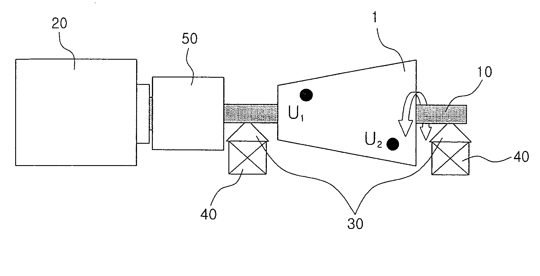
[0021]1: rotational body[0022]10: rotational shaft[0023]20: simple harmonic angular vibration generator[0024]30: support[0025]40: force or vibration transducer[0026]50: angular vibration measuring sensor

BEST METHOD FOR CARRYING OUT THE INVENTION

[0027]Practical and presently preferred embodiments of the present invention are illustrative as shown in the following embodiment.

[0028]However, it will be appreciated that those skilled in the art, on consideration of this disclosure, may make modifications and improvements within the spirit and scope of the present invention.

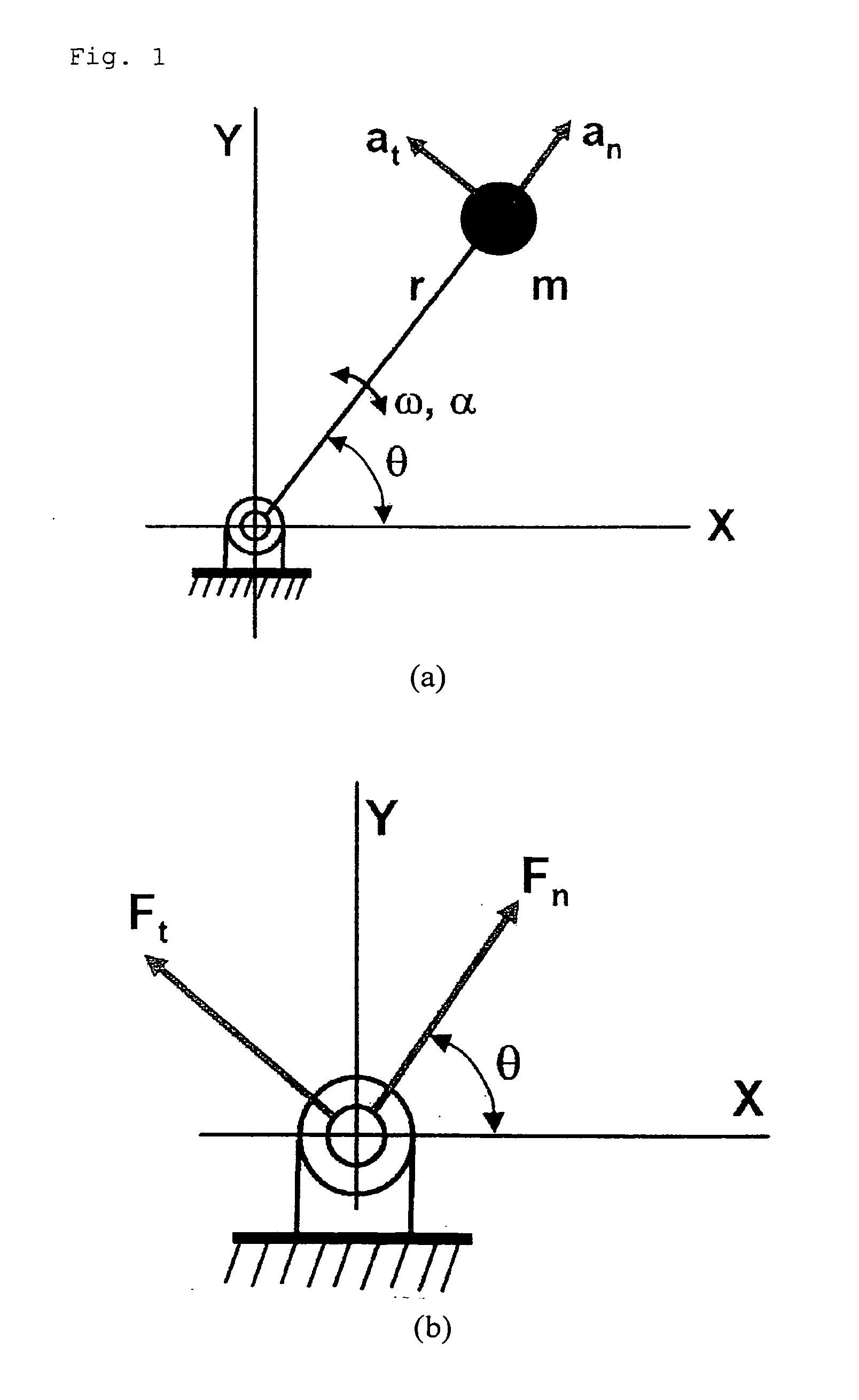
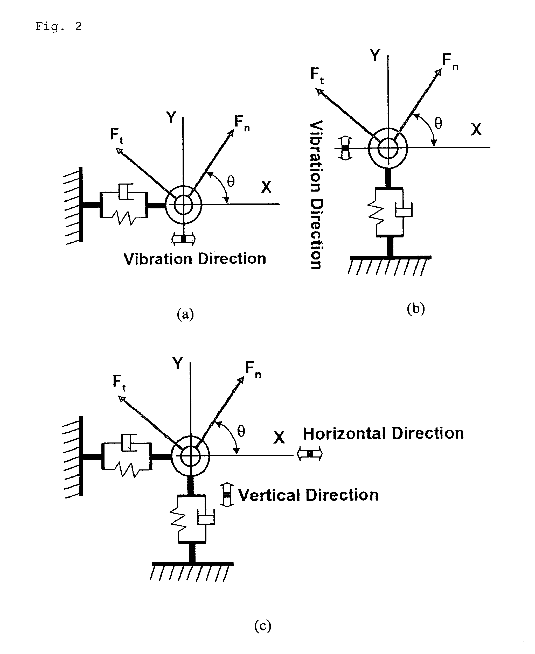
[0029]FIG. 1 is conceptual drawings showing the force components exerted to the support and acceleration components of an unbalanced mass and FIG. 2 is schematic drawings showing the vibration models of the support. FIG. 3 is a configuration drawing showing the structure of a dynamic balancing apparatus using a simple harmonic angular motion, i.e. a periodic angular vibration.

[0030]In a simple harmonic motion having th...


PUM


Abstract

Provided is a dynamic balancing apparatus using a simple harmonic angular motion, including a rotational shaft on which a rotational body having an unbalanced mass is installed; a simple angular motion generator for periodically vibrating the rotational shaft; a support for supporting both sides of the rotational shaft; an angular vibration measuring sensor for measuring the simple harmonic angular motion of the rotational shaft; and force or vibration transducers for measuring applied force acting on or vibration transferred to the support by means of the simple harmonic motion of the unbalance mass.

Description

TECHNICAL FIELD[0001]The present invention relates to a dynamic balancing apparatus and effective balancing methods using a simple harmonic angular motion, which can precisely measure the angle and magnitude of the unbalanced mass of a rotational body using angular vibration, i.e., a simple harmonic angular vibration having the rotational amplitude and period.BACKGROUND ART[0002]All components of a rotating machine are primarily machined along the rotational axis of manufacturing machinery thereof. A dynamic balancing apparatus is used to measure the position, i.e., angle, and magnitude of an unbalanced mass which exists with respect to an actual rotational axis after the components are assembled.[0003]A dynamic balancing method is a theoretical method which is used in the dynamic balancing apparatus to measure the position, and magnitude of a rotating unbalanced mass.[0004]In order to measure the unbalancing mass, most commercially used dynamic balancing apparatuses are used to mea...

Claims


Application Information

Patent Timeline
Patent Type & Authority Applications(United States)
IPC IPC(8): G01M1/16
CPCG01M1/24G01M1/16
Inventor CHEUNG, WAN SUPLIM, JONG YEONYOON, SAE WON
Owner KOREA RES INST OF STANDARDS & SCI
Learn More