Centrifugal Fan and Air Conditioner Using the Same

a centrifugal fan and centrifugal fan technology, applied in lighting and heating apparatus, heating types, applications, etc., can solve the problems of insufficient prevention of noise resulting from separated flows, insufficient prevention of rotating fans, and insufficient prevention of separate flows, so as to maintain generation capacity, prevent eddies, and efficiently genera

Inactive Publication Date: 2009-10-15
DAIKIN IND LTD
View PDF14 Cites 13 Cited by
  • Summary
  • Abstract
  • Description
  • Claims
  • Application Information

AI Technical Summary

Benefits of technology

[0011]Accordingly, it is an objective of the present invention to provide a centrifugal fan having a novel construction applicable to general air conditioners, which centrifugal fan is capable of making uniform air velocity distribution in the height direction of the impellers at the blow-out port of the centrifugal fan by suppressing separated flows generated in the vicinity of the fan blow-out port on the surface of a shroud facing the main plate, and capable of reducing running noise of the centrifugal fan. Also, it is another objective of the present invention to provide an air conditioner capable of reducing running noise by using a thus constructed centrifugal fan, in an air conditioner having a centrifugal fan mounted therein.
[0022]It is preferable that the centrifugal fan is a turbo fan. With such a construction, the fan efficiency is improved. At the same time, the running noise is further suppressed.

Problems solved by technology

However, the turbo fan according to Patent Document 1 cannot sufficiently prevent separated flows generated in the vicinity of the fan blow-out port on the surface of the shroud facing the main plate.
For this reason, noise resulting from the separated flows cannot be sufficiently prevented from occurring.
Further, in an air conditioner having a turbo fan according to Patent Document 1 mounted therein, there is still a problem in that running noise in the air conditioner employing the turbo fan according to Patent Document 1 is still great.
As a result, there is still another problem in that the energy efficiency of the air conditioner is lowered.
In addition, having a special shape, the impellers of the turbo fan according to Patent Document 1 are not applicable to a centrifugal fan of a general air conditioner.

Method used


Image

  • Centrifugal Fan and Air Conditioner Using the Same
  • Centrifugal Fan and Air Conditioner Using the Same
  • Centrifugal Fan and Air Conditioner Using the Same

Examples


Embodiment Construction

[0034]Hereinafter, a description is given of a centrifugal fan and an air conditioner having the centrifugal fan according to one embodiment of the present invention with reference to the accompanying drawings.

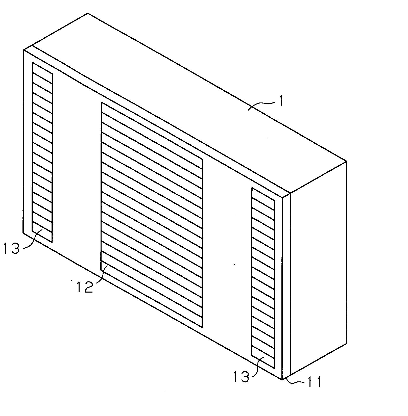
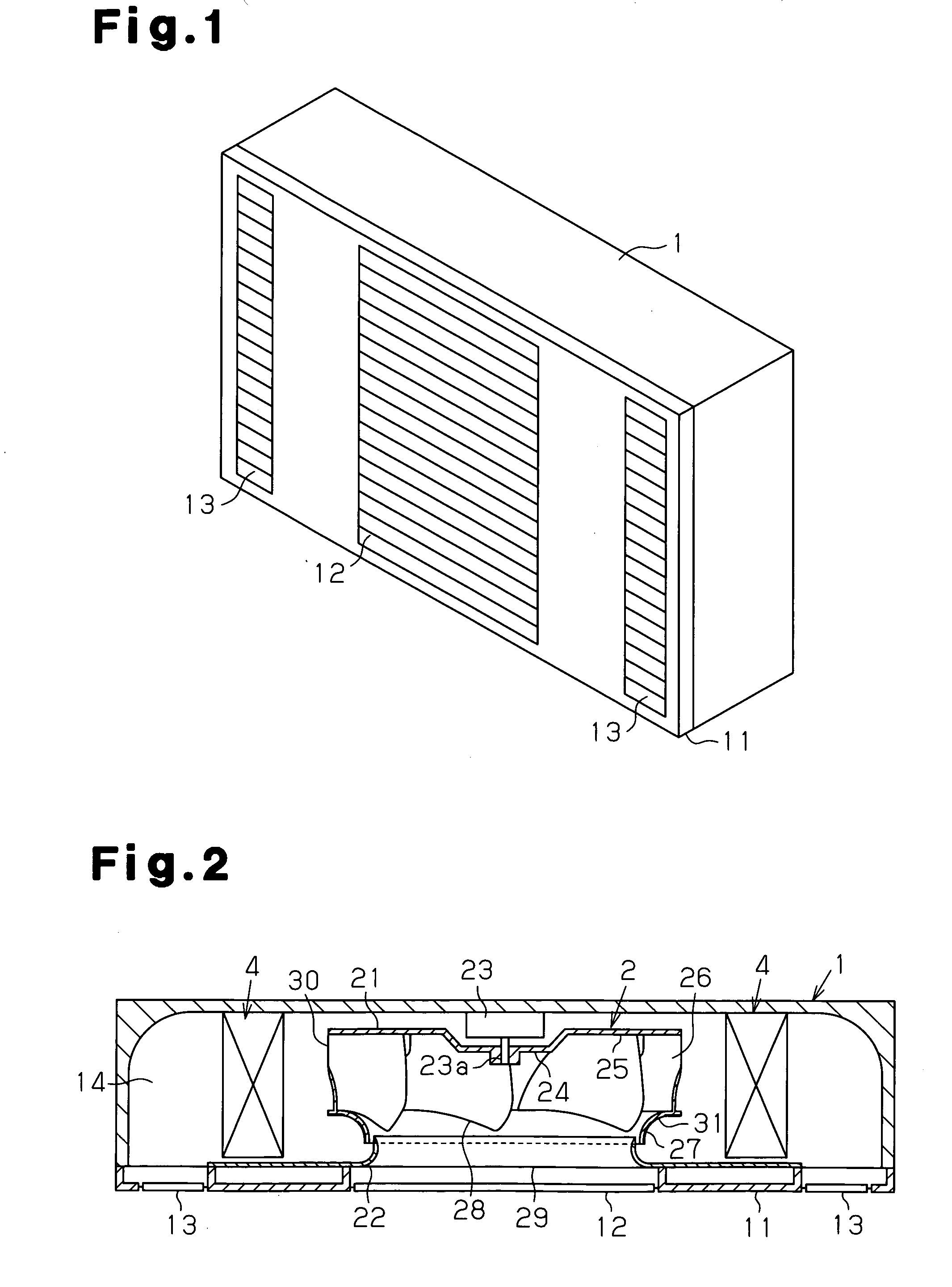
[0035]An air conditioner according to the present embodiment is an indoor unit for a wall type air conditioner, and has a laterally long box shape as shown in the perspective view of FIG. 1. The indoor unit is formed, as shown in the plan cross-sectional view of FIG. 2, so that the thickness direction (the vertical direction in FIG. 2) becomes smaller. A turbo fan 2 operating as an indoor fan and heat exchangers 4 for cooling or heating indoor air are accommodated in a main body casing 1.

[0036]The main body casing 1 is provided with a front plate 11 at the front side of the main body casing 1 as shown in the perspective view of FIG. 1. The front plate 11 is provided with an air suction port 12 for drawing in air at the middle part thereof, and is provided with air blow-out por...


PUM


Abstract

The present invention provides a centrifugal fan by which air velocity distribution in the height direction of impellers at a fan blow-out port is made uniform and running noise is reduced, and an air conditioner whose running noise is reduced by applying the centrifugal fan thereto. The centrifugal fan is provided with a hub for fixing the rotary shaft of a motor, a main plate formed on the outer circumference of the hub, a shroud disposed to be opposed to the main plate, which forms an air passage, a plurality of impellers disposed between the main plate and the shroud, and a bellmouth disposed at the suction side of the shroud. Projections or recesses are formed on the surface of the shroud facing the bellmouth, which projections or recesses form air streams flowing from the center of the shroud toward the outer circumference thereof along the surface when running a fan. The air conditioner has a thus constructed centrifugal fan mounted therein.

Description

TECHNICAL FIELD[0001]The present invention relates to a centrifugal fan and an air conditioner using the same, in particular to a technology to reduce noise of the centrifugal fan and air conditioner using the same.BACKGROUND ART[0002]Generally, a centrifugal fan has been frequently employed for an air conditioner because it is highly efficient and low in noise level. Also, a ceiling built-in type air conditioner has been frequently utilized in recent years for commercial use, and a wall type air conditioner has been frequently utilized in households. In any of these air conditioners, there are many cases where such a construction is employed in which a heat exchanger is disposed at the blow-out side of a centrifugal fan to reduce the size.[0003]Thus, in the construction in which a heat exchanger is disposed at the blow-out side of a centrifugal fan, there are many cases where the length of the impellers in the axial direction, that is, the height of the impellers is increased in co...

Claims


Application Information

Patent Timeline
Patent Type & Authority Applications(United States)
IPC IPC(8): F28F13/12F04D29/66F24F1/0022F04D29/28F24F1/0063
CPCF04D29/162F04D29/4213F24F1/0007F04D29/667F24F2001/0048F24F1/0022F04D29/281F24F2001/0037F24F1/0047F24F1/0057F24F1/0063F04D29/28F04D29/44F24F1/00
Inventor ZHENG, ZHIMINGOHNISHI, TADASHI
Owner DAIKIN IND LTD
Why Eureka
Try Eureka