3-Wheeled stand-up personal mobility vehicle and components therein

a personal mobility vehicle and stand-up technology, applied in the field of electric vehicles, can solve the problems of steep learning curve, rider fatigue, vehicle instability, etc., and achieve the effects of reducing the risk of vehicle rollover accidents, reducing the lateral sway, and reducing the sway

Inactive Publication Date: 2009-10-15
RIDE VEHICLES
View PDF19 Cites 41 Cited by
  • Summary
  • Abstract
  • Description
  • Claims
  • Application Information

AI Technical Summary

Benefits of technology

[0005]Mainly through such improved design, the vehicle is more stable and less likely to tip over when the rider turns the vehicle, the rider experiences less fatigue, routine maintenance and repair are made easier, shipping costs are reduced, electronics are less vulnerable to water damage or severe impact and manufacturing costs are reduced.
[0011]There are four sub-assemblies for the vehicle. They are the front fork assembly, handlebar assembly, trailing arm assembly, and main chassis. These four sub-assemblies are fastened together using widely available hardware and common hand tools. Unlike prior designs, these sub assemblies do not require complex fabrication techniques such as welding in order to complete final assembly. The advantage is reduced labor costs for final assembly during the manufacturing process.

Problems solved by technology

These designs have often resulted in problems such as vehicle instability, rider fatigue, steep learning curves, electronics that are vulnerable to inclement weather, time-consuming assembly, complex maintenance procedures, and awkward or costly shipping.

Method used


Image

  • 3-Wheeled stand-up personal mobility vehicle and components therein
  • 3-Wheeled stand-up personal mobility vehicle and components therein
  • 3-Wheeled stand-up personal mobility vehicle and components therein

Examples


Embodiment Construction

[0029]The features and the advantages of the present invention will be more readily understood upon a thoughtful deliberation of the following detailed description of a preferred embodiment of the present invention with reference to the accompanying drawings.

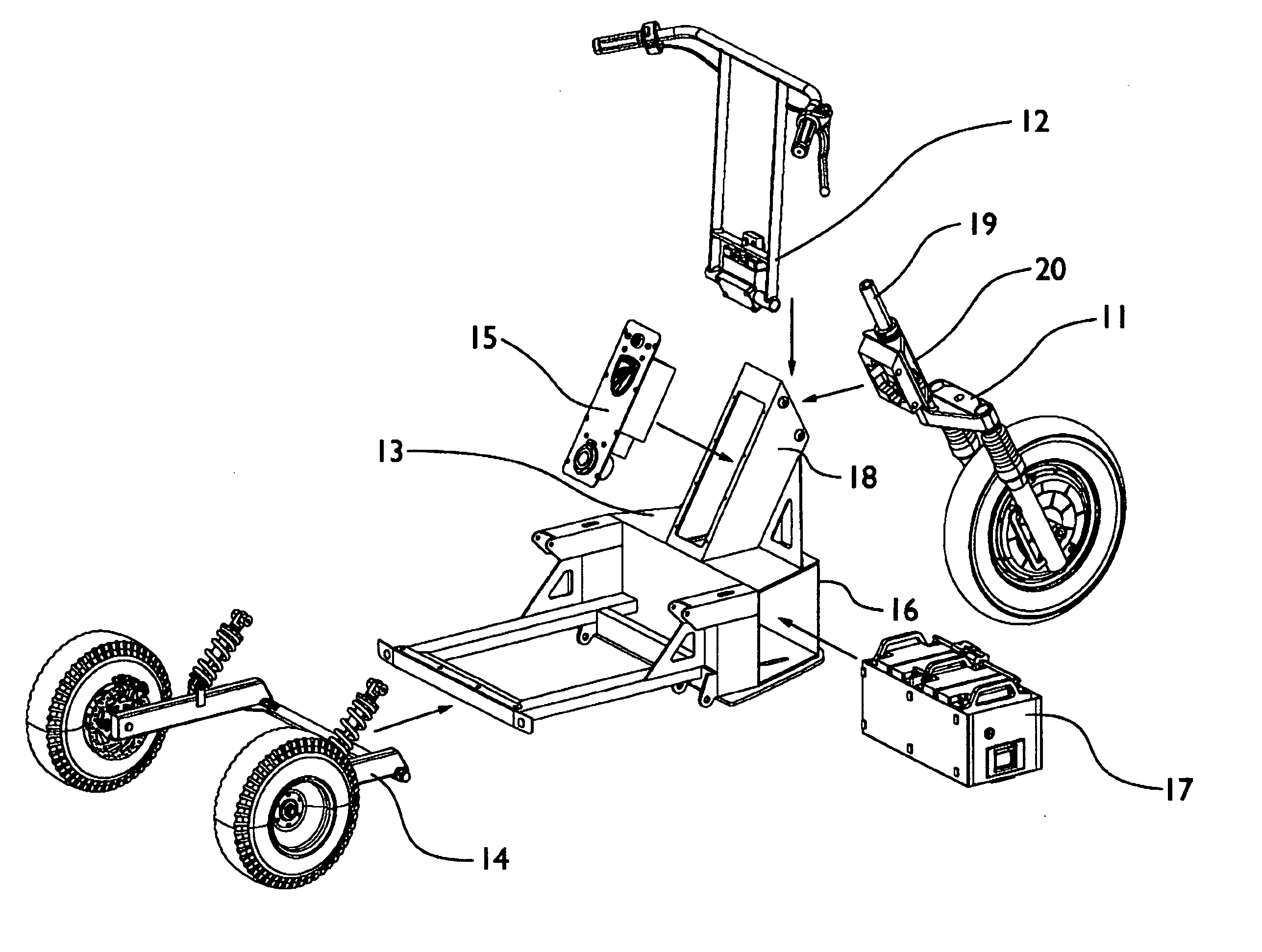
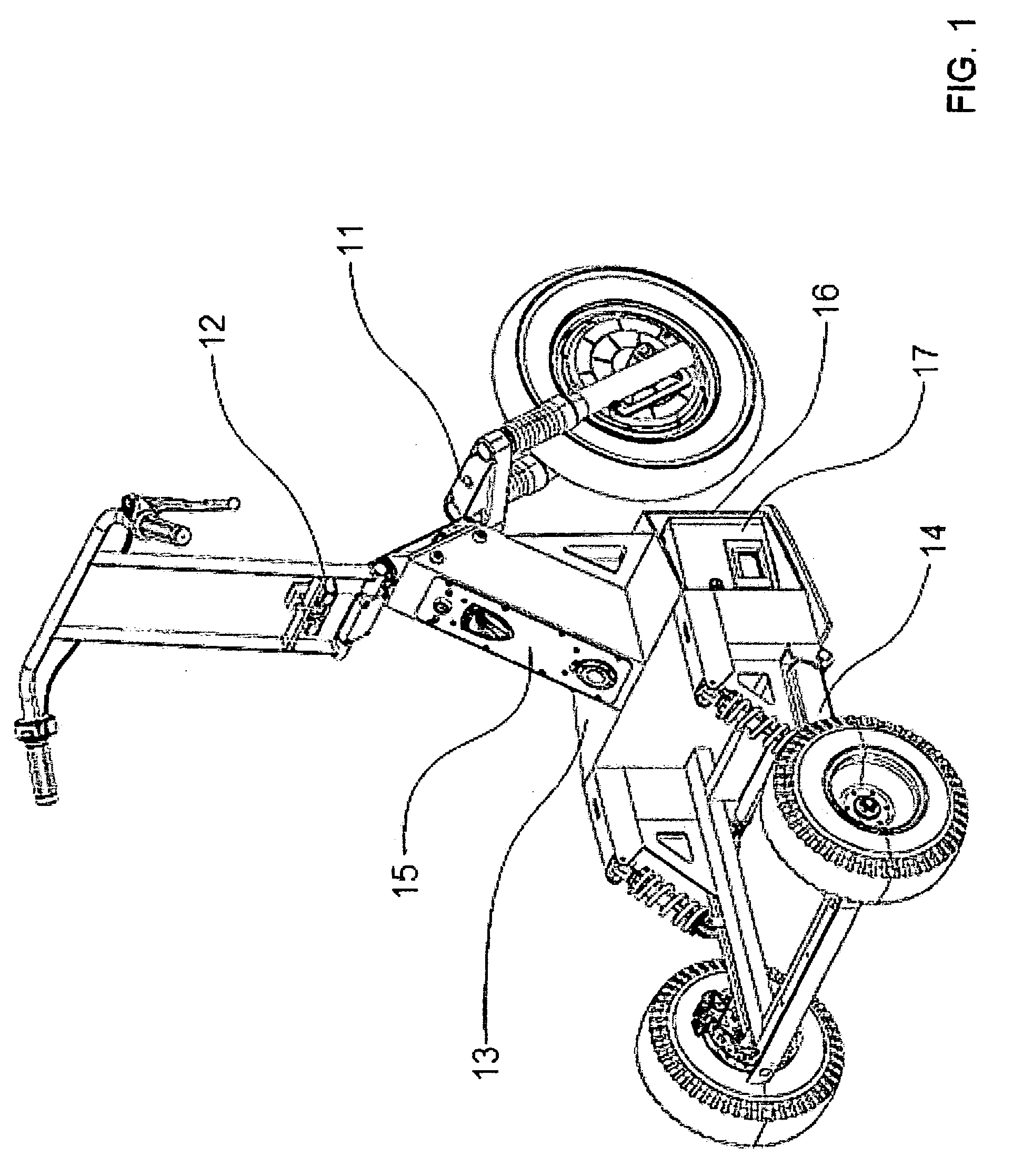
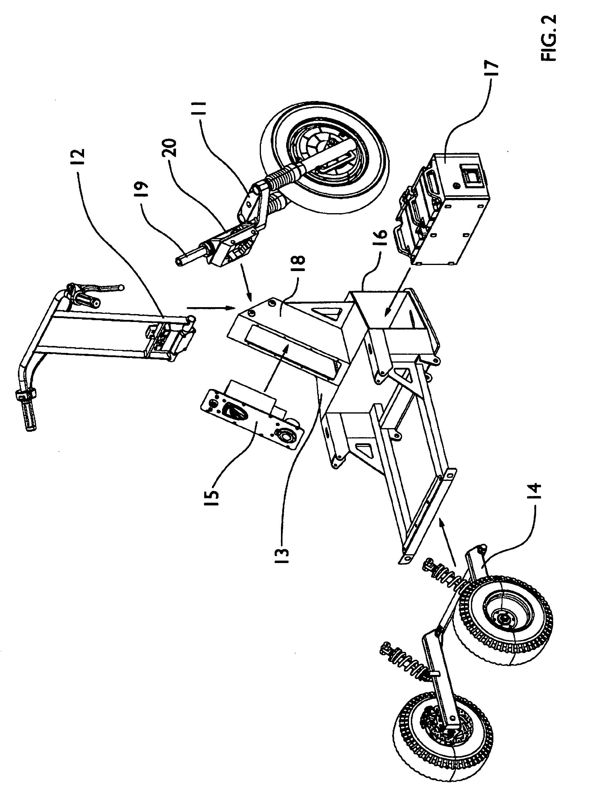
[0030]As shown in FIGS. 1-2, an electric vehicle with modular chassis embodied in the present invention comprises a front fork assembly 15, and 11, a handlebar assembly 12, a main chassis 13, a trailing arm assembly 14, an electronics plate a battery pack 17. Among these, the front fork assembly 11 is bolted to the main chassis 13. The handlebar assembly 12 is fastened to the steer tube 19 which protrudes from the top of the head tube 20. The trailing arm assembly 14 bolts to the main chassis 13 and pivots to provide suspension for the rear of the vehicle. The powertrain electronics plate 15 fastens into the primary vertical chassis member 28. The battery pack 17 slides into the primary horizontal chassis member 29. By placing t...


PUM


Abstract

An electric vehicle with a modular frame that includes a main chassis with a rider platform (standing position), front fork / wheel assembly, handlebar assembly, and rear trailing arm assembly with left and right rear wheels. The front fork assembly bolts to the main chassis. The handlebar assembly fastens to the pivoting steer tube of the front fork assembly. The trailing arm assembly bolts to the main chassis and pivots to provide rear suspension for the vehicle. The trailing arm includes a stabilizer bar connecting the right and left trailing arms. Electronics enclosures are integral to the main chassis and are structural members of the vehicle. The battery pack can be installed or removed from the main chassis with a hand-activated latch. The electronics plate contains traction system electronics and is removable from the main chassis. The handle bar assembly includes a folding mechanism.

Description

FIELD OF THE INVENTION[0001]The present invention relates generally to an electric vehicle and more particularly to an electric vehicle with a standing rider.BACKGROUND OF THE INVENTION[0002]In the field of electric vehicles and more particularly two and three-wheeled electric scooters, previous inventors have created many designs for chassis, suspension, and electric powertrains. These designs have often resulted in problems such as vehicle instability, rider fatigue, steep learning curves, electronics that are vulnerable to inclement weather, time-consuming assembly, complex maintenance procedures, and awkward or costly shipping.[0003]In light of this, the inventors, based on the experiences of designing and developing related products for many years, aimed at the above problems, and after detailed design and cautious evaluation, ultimately obtained an invention of real practicability.BRIEF SUMMARY OF THE INVENTION[0004]The facts of improving functionality and effectiveness by thi...

Claims


Application Information

Patent Timeline
Patent Type & Authority Applications(United States)
IPC IPC(8): B62K15/00B60K1/00B62K21/16
CPCB60K2001/0461B60Y2200/12B62D51/02B62K3/002Y10T74/20816B62K2204/00B60K1/04Y10T74/20792B62K5/027
Inventor KASABA, MICHAEL EDWARDHUFF, BRIAN ROBERTLEHNHARDT, AARON JAMES
Owner RIDE VEHICLES
Why Eureka
Try Eureka