a soybean milk machine

A soymilk machine and machine head technology, applied in kitchen utensils, home utensils, beverage preparation devices, etc., can solve problems such as no good solution, foam overflow, etc., to improve the aesthetics, not easy to overflow, and reduce the difficulty of cleaning. Effect

Active Publication Date: 2020-04-14
JOYOUNG CO LTD
View PDF7 Cites 0 Cited by
  • Summary
  • Abstract
  • Description
  • Claims
  • Application Information

AI Technical Summary

Problems solved by technology

[0007] The present invention aims at solving the foam overflow problem of the existing soymilk maker without a good solution. The existing solution method of increasing the volume of the cup is in line with people's demand for thinner and smaller soymilk maker problem of great contradiction

Method used


Image

  • a soybean milk machine
  • a soybean milk machine
  • a soybean milk machine

Examples


Embodiment 1

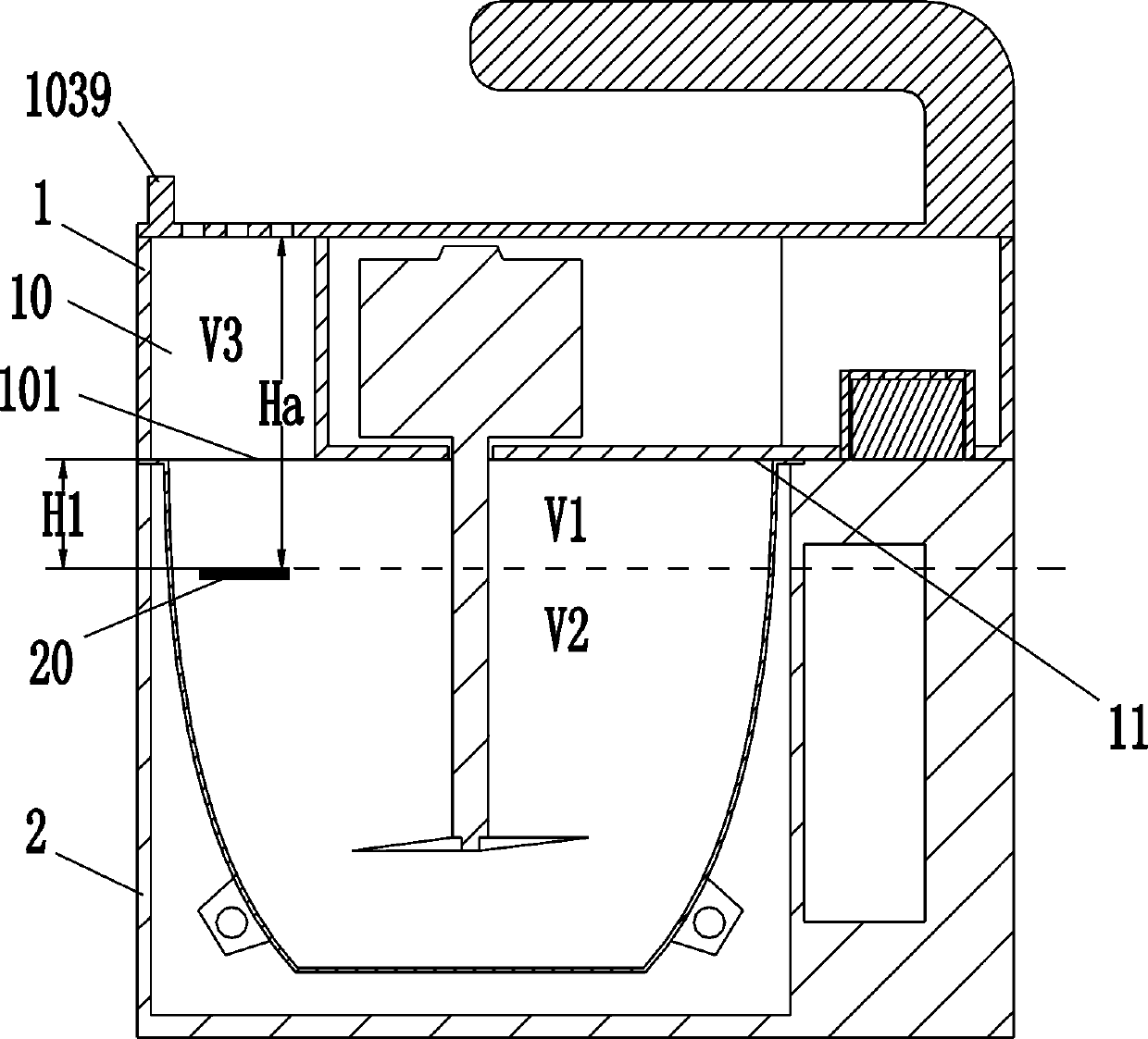
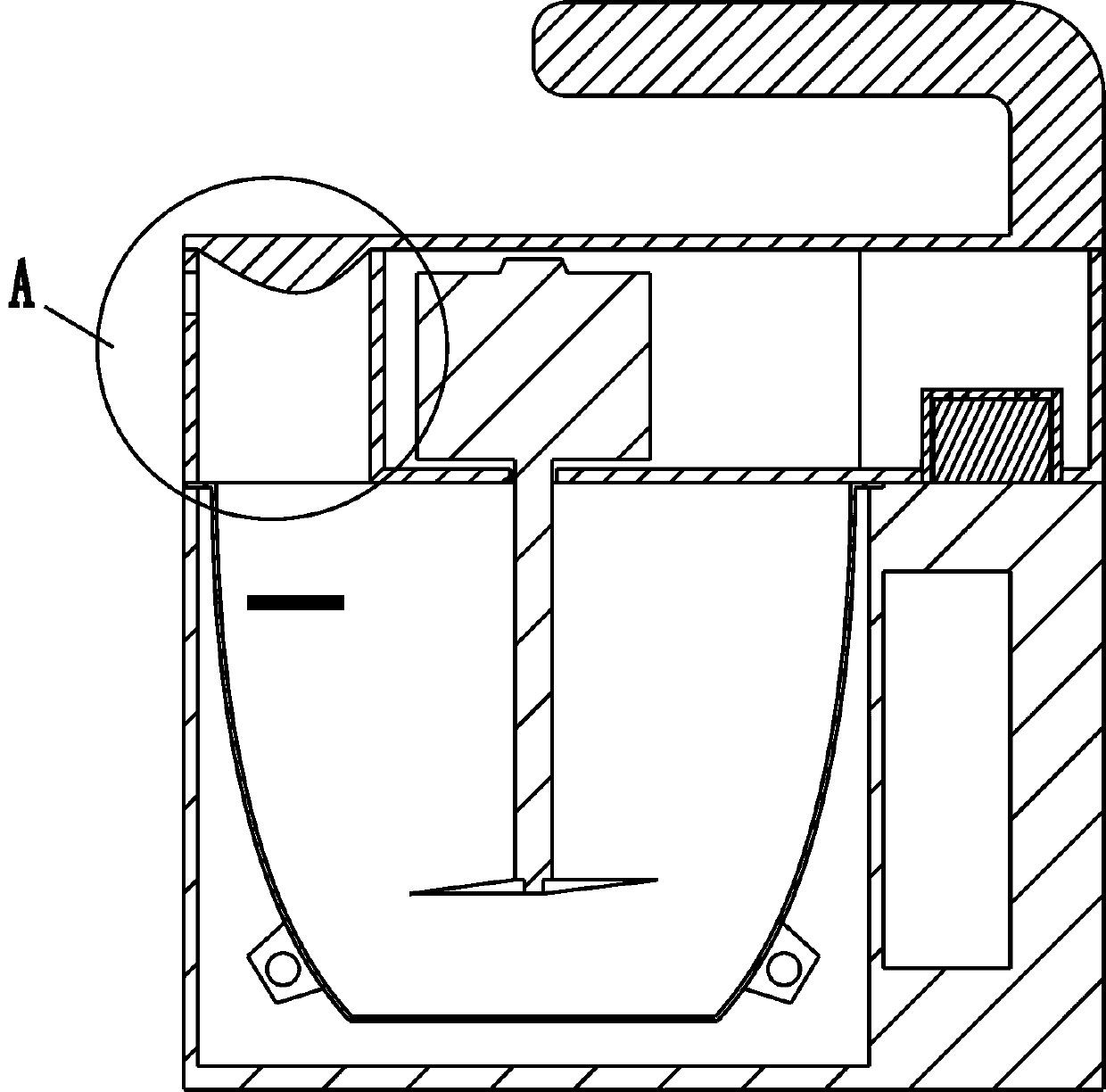
[0049] Such as figure 1 , figure 2 Shown is a schematic structural diagram of the first embodiment of the present invention. A soybean milk machine, comprising a machine head 1 and a cup body 2, the machine head is placed on the cup body, a water level marking line 20 is arranged on the side wall of the cup body, and the junction of the machine head 1 and the cup body 2 Seal fit, located above the water level marking line 20, the machine head 1 is provided with an anti-overflow chamber 10 with a bottom opening 101, the cup body 2 communicates with the anti-overflow chamber 10 through the bottom opening 101, and the slurry in the cup body It enters into the anti-overflow chamber 10 through the bottom opening 101 .

[0050] In this embodiment, the machine head 1 has a mounting surface 11 mounted on the rim of the cup, and the bottom opening 101 of the anti-overflow cavity is located on the plane where the mounting surface 11 is located. The holding surface 11 has the functio...

Embodiment 2

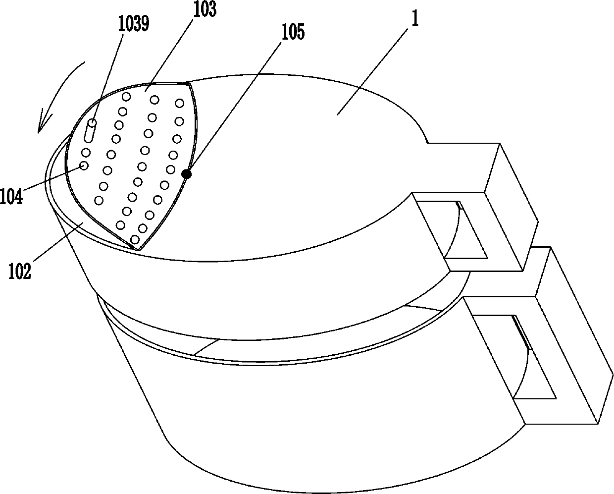
[0068] Such as image 3 , Figure 4 Shown is a schematic structural diagram of the second embodiment of the present invention. The difference between this embodiment and Embodiment 1 is that the cover plate in this embodiment is an anti-overflow cover 1030 for anti-overflow and defoaming of the slurry, and its bottom has a liquid collecting part protruding into the anti-overflow chamber 10, Wherein, the liquid collecting portion is a gradual protrusion 1031 formed from the edge of the spill-proof cover 1030 to the center of the spill-proof cover 1030, and the top opening edge of the spill-proof chamber 10 is provided with a support step 1021 supporting the spill-proof cover 1030, The anti-overflow cover 1030 is held on the support step 1021. In addition, a steam channel 106 communicating with the outside atmosphere of the machine head is also provided on the side wall of the anti-overflow chamber 10. The steam channel 106 can be used to evacuate part of the steam through the ...

Embodiment 3

[0072] Such as Figure 5 Shown is a schematic structural view of the third embodiment of the present invention. The difference between this embodiment and Embodiment 1 is that in this embodiment, the machine head includes a machine head body 12 and an anti-overflow assembly 13 detachably connected to the machine head body 12, and the anti-overflow chamber 10 is set On the anti-overflow assembly 13, and located above the anti-overflow assembly 13, an extension piece 14 connected to the top opening 102 of the anti-overflow chamber 10 is provided, and an expansion chamber 140 and an overfill-proof chamber are formed in the extension piece 14. 10 connectivity.

[0073] In this embodiment, the anti-overflow component with the anti-overflow cavity is detachably connected to the machine head body, which can facilitate cleaning of the anti-overflow cavity. Moreover, the expansion chamber is a supplement to the anti-overflow chamber, which can prevent the occurrence of pulp overflow ...


PUM


Abstract

The invention relates to small electric appliances in kitchens, in particular to a soybean milk machine. The soybean milk machine comprises a machine head and a cup body, the machine head is placed onthe cup body, and a water level identification line is arranged on the side wall of the cup body; the soybean milk machine is characterized in that the junction of the machine head and the cup body is located above the water level identification line through sealed cooperation, the machine head is provided with a spill-proof cavity with a bottom opening, the cup body is communicated with the spill-proof cavity through the bottom opening, and soybean milk in the cup body enters the spill-proof cavity through the bottom opening. By adopting the technical scheme, compared with the prior art, thesoybean milk machine has the advantages that the utilization rate of the inner space of the cup body of the soybean milk machine is higher, and the situation is avoided that a large-capacity cup bodycan only produce a smaller amount of soybean milk drink; meanwhile, the soybean milk machine can achieve thinning, lightweight and miniaturization, the machine head is more convenient to clean, and the whole machine is more attractive.

Description

technical field [0001] The invention relates to small kitchen appliances, in particular to a soybean milk maker. Background technique [0002] At present, the structure of the mainstream soybean milk machine on the market is mainly composed of a cup body and a machine head, and the machine head is buckled on the cup body. A motor is arranged in the machine head, and the output shaft of the motor stretches out from the end face of the lower cover and extends into the water, and a crushing cutter is installed at the end of the motor shaft. Due to the characteristics of soybeans, the soymilk machine will produce a lot of foam when boiling the soymilk. In order to avoid foam overflow, the existing soymilk machine generally adopts a relatively large cup body, and pre-set it above the marking line of the amount of pulp produced in the cup body. A large anti-overflow space is left, which makes the effective volume of the cup body smaller and the utilization rate of the space is lo...

Claims


Application Information

Patent Timeline
Patent Type & Authority Patents(China)
IPC IPC(8): A47J31/00A47J31/44A47J43/044A47J43/07
CPCA47J31/00A47J31/4403A47J43/044A47J43/0711
Inventor 王旭宁刘爽周之征章佳锋
Owner JOYOUNG CO LTD
Why Eureka
Try Eureka