
Low pressure backwash

Inactive Publication Date: 2009-10-15
EVOQUA WATER TECH LLC
View PDF101 Cites 40 Cited by
  • Summary
  • Abstract
  • Description
  • Claims
  • Application Information

AI Technical Summary

Benefits of technology

[0004]It is an object of the present invention to overcome or ameliorate at leas

Problems solved by technology

Many of these systems require complex and expensive ancillary equipment to provide the necessary flow to liquid and / or gas to achieve efficient cleaning.

Method used


Image

  • Low pressure backwash
  • Low pressure backwash
  • Low pressure backwash

Examples


Embodiment Construction

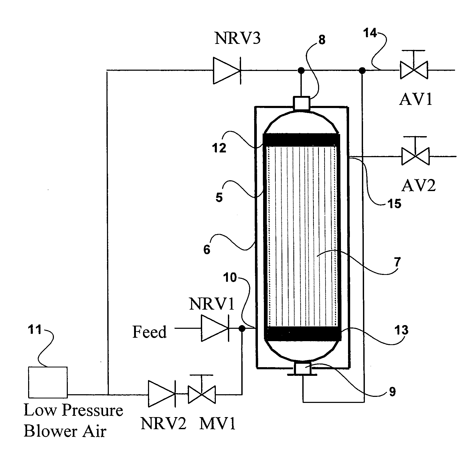
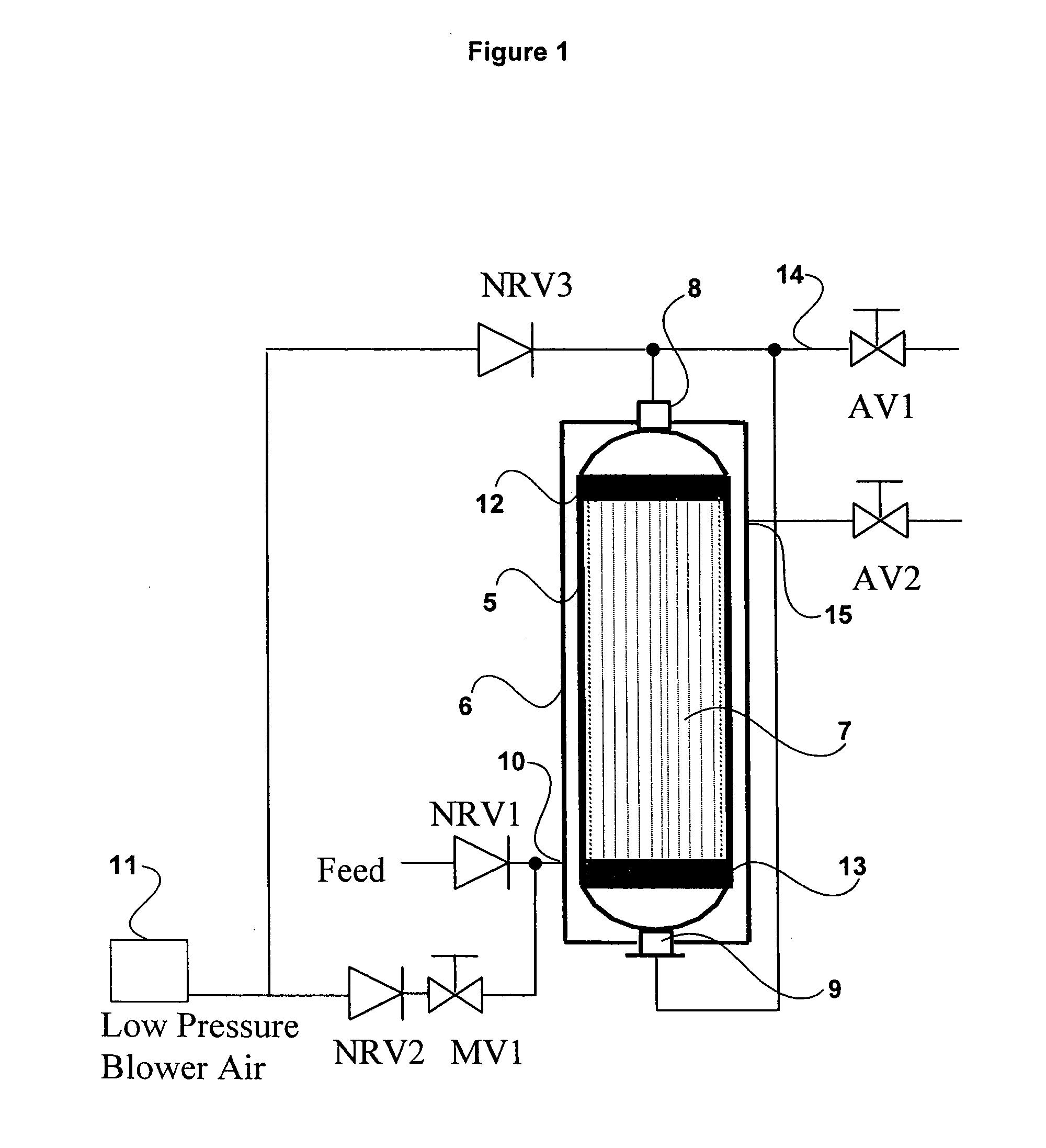
[0042]Referring to FIG. 1, the hollow fibre membrane module 5 is mounted in a pressure vessel 6 and the filtration flow is from the shell side into the fibre lumens 7. The module 5 is connected to upper and lower permeate outlets 8 and 9, respectively. When the filtration process is suspended for a cleaning cycle, the lumens 7 remain filled with permeate.

[0043]Feed is supplied to the vessel 6 through an inlet port 10 adjacent the lower end of the module 5 through a non-return valve NRV1. Low-pressure blower gas, typically air, is supplied to the inlet port 10 through a non-return valve NRV2 and manually operated control valve MV1. Low-pressure blower air is also fed from a blower 11 to the upper permeate outlet 8 through non-return valve NRV3. Permeate is withdrawn from the membrane lumens through the upper and lower headers 12 and 13 and respective upper and lower module permeate outlets 8 and 9. The withdrawn permeate flows through a permeate line 14 controlled by valve AV1. The p...


PUM

PropertyMeasurementUnit
Pressureaaaaaaaaaa
Pressureaaaaaaaaaa
Pressureaaaaaaaaaa

Abstract

A method of backwashing a membrane filtration system comprising at least one permeable hollow membrane, the method comprising the step of applying a low-pressure gas to the permeate remaining present in the system when the filtration process is stopped or suspended to provide liquid for backwashing the pores of the membrane during a backwashing process.

Description

TECHNICAL FIELD[0001]The present invention relates to membrane filtration systems and more particularly to methods and systems for backwashing such systems.BACKGROUND OF THE INVENTION[0002]Backwashing of membrane filtration systems is important part of maintaining the operating efficiency of such systems. A variety of different methods and arrangements are used. Porous membrane filtration systems require regular backwashing of the membranes to maintain filtration efficiency and flux while reducing transmembrane pressure (TMP) which rises as the membrane becomes fouled with impurities. Typically, during the backwash cycle, the foulant is removed from the membrane by pressurised gas, liquid or both into the feed tank or cell. The liquid containing impurities and deposits from the membranes is then drained or flushed from the tank. Further cleaning of the membranes may be provided by scouring the surface of the membranes with gas bubbles.[0003]Many of these systems require complex and ...

Claims


Application Information

Patent Timeline
IPC IPC(8): B01D65/02B01D61/00
CPCB01D65/02B01D2311/14B01D2313/24C02F2303/16B01D2321/12B01D2321/2066C02F1/44B01D2321/04B01D65/08
Inventor BILTOFT, BRUCE GREGORYCAO, ZHIYILAZAREDES, HUW ALEXANDERZHA, FUFANGLY, LYVONNE
Owner EVOQUA WATER TECH LLC
Learn More