
Electron capture dissociation in radiofrequency ion traps

a radiofrequency ion and electron capture technology, applied in the direction of isotope separation, electric discharge tubes, separation processes, etc., can solve the problems of ptm site neutral loss, energy randomization, and insufficient energy in any particular bond to cause it to break

Inactive Publication Date: 2009-10-15
SYAGEN TECH
View PDF3 Cites 5 Cited by
  • Summary
  • Abstract
  • Description
  • Claims
  • Application Information

AI Technical Summary

Benefits of technology

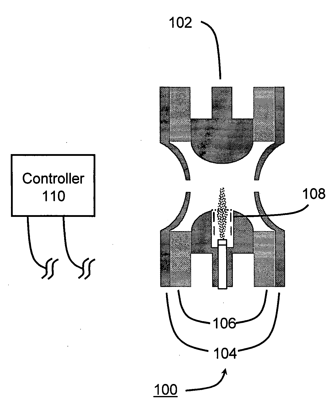
"The patent describes a detector system that has an ion trap and an electron source. The system has a controller that can turn the ion trap and electron source on and off. This means that the electron source is always on when the ion trap is turned off. The technical effect of this system is that it allows for better control and manipulation of the ion trap, which can improve the accuracy and sensitivity of the detector."

Problems solved by technology

Also as molecules increase in size (e.g., proteins), energy randomization becomes so extensive that there is not sufficient energy in any particular bond to cause it to break.
Fragmentation by CID often leads to neutral loss of PTM sites complicating the identification of the sequence and the location of the PTM group.
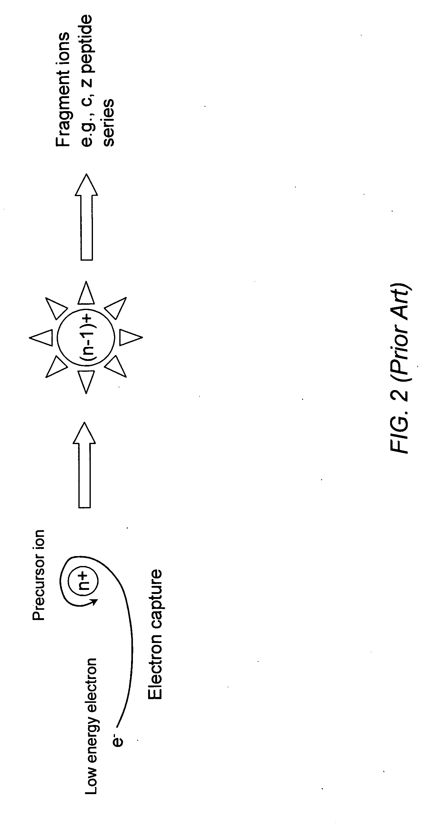
ECD is difficult to implement in radiofrequency (RF) driven mass analyzers, such as quadrupole and linear ion traps (QIT and LIT, respectively) because the RF fields accelerate the electrons to energies that greatly exceed what is needed for efficient ECD.
The difficulty of this method is that the electrons remain cool for less than one period of the ring electrode RF (i.e., about 1 microsecond) resulting in inefficient ECD and reactions leading to undesired fragmentation.
No magnet is needed by this method; however, the electrons were injected well outside the ion trap, which made it difficult to decelerate and localize the electrons at the center of the ion trap.
Consequently, very long ECD interaction times (e.g., 400 ms / scan×250 scans=100 s) were required, which is not amenable to use with chromatography.
A disadvantage of this method is complexity as it required a second linear ion trap positioned orthogonal to the ion path leading to the TOFMS, as well as the use of a permanent magnet.
However, in this method the effective reaction times are very short because of the immediate reacceleration of the electrons in the RF field.
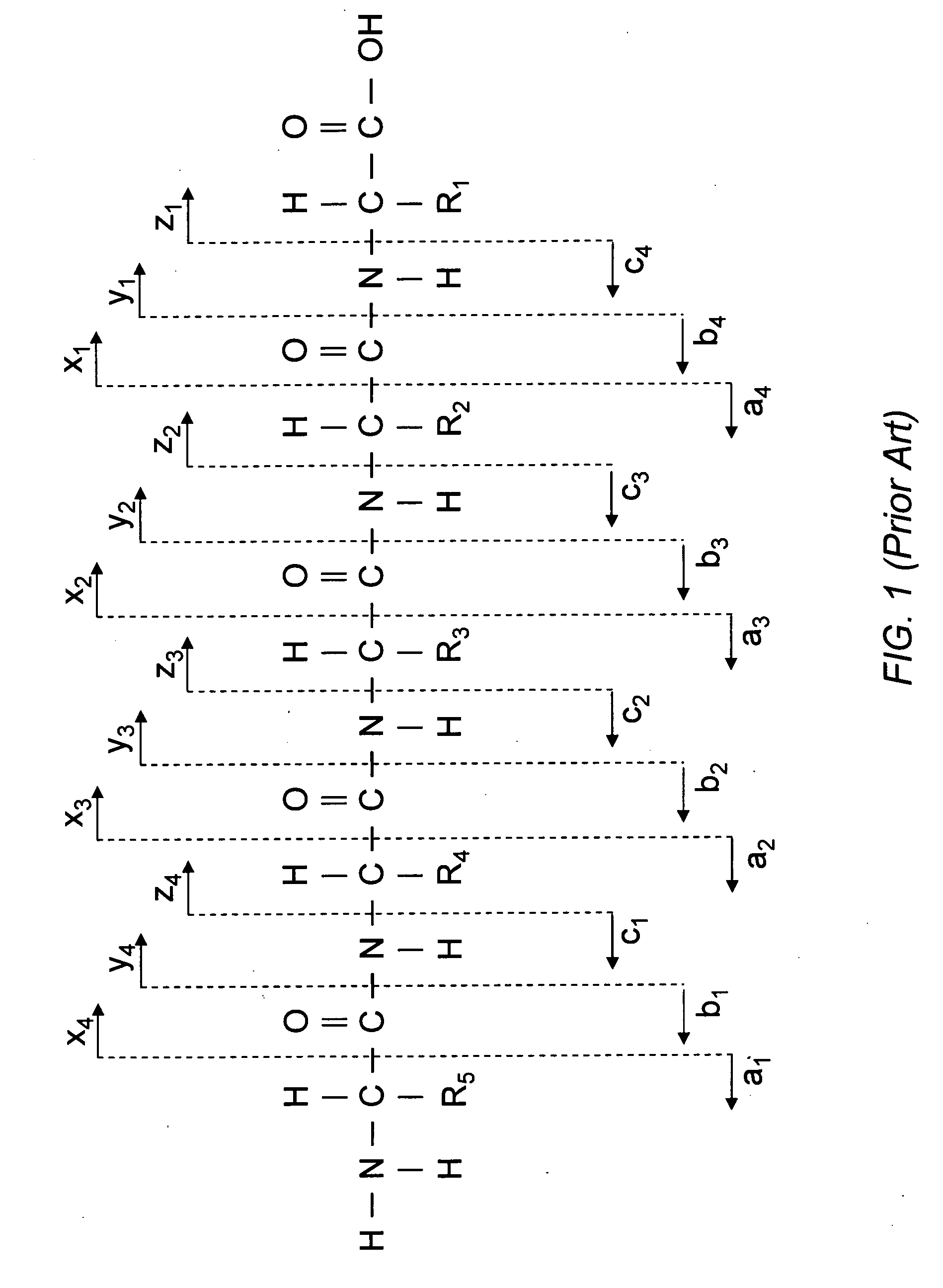
However, this method does not give the selective N—Ca bond breakage that gives the informative c and z series of peptide ion fragments shown in FIG. 1.
This patent does not provide disclosures for performing ECD in an RF ion trap or ion guide.

Method used


Image

  • Electron capture dissociation in radiofrequency ion traps
  • Electron capture dissociation in radiofrequency ion traps
  • Electron capture dissociation in radiofrequency ion traps

Examples


Embodiment Construction

[0026]Disclosed is a system and method that includes injecting low-energy electrons in a radiofrequency (RF) ion trap in order to dissociate positive ions by electron capture. The system includes an ion trap, a controller to provide RF that can be switched on and off rapidly, and a source of low-energy electrons that can be turned on and off synchronously with the radiofrequency on / off periods. The RF can be applied to the ring electrode of a QIT and to the linear electrodes of a LIT. The disclosed method can be used with other ion multiple guides that operate with RF. It can also be applied to QIT, LIT, and other multiple ion guides that serve for ion storage only and also for mass analysis.

[0027]In order to deliver a beam of low-energy electrons into an ion trap it is necessary to have a constant voltage potential in the region of greatest ion density so that the electrons are not accelerated. This can be achieved by turning the RF applied to the ion trap momentarily off and turni...


PUM


Abstract

A system and method that includes injecting low-energy electrons in a radiofrequency (RF) ion trap in order to dissociate positive ions by electron capture. The system includes an ion trap, a controller to provide RF that can be switched on and off rapidly, and a source of low-energy electrons that can be turned on and off synchronously with the radiofrequency on / off periods.

Description

BACKGROUND OF THE INVENTION[0001]1. Field of the Invention[0002]The present invention relates to a device and method for achieving electron capture dissociation in radiofrequency ion traps in order to effect selective dissociation of molecular ions.[0003]2. Background Information[0004]Mass spectrometry (MS) analysis of proteins and peptides is a critical function in proteomic studies. MS instrumentation enables selective ion fragmentation that can give structure and sequence information of peptides and proteins leading to identification and in some cases the function of protein in cellular processes. The principal means of achieving sequence information is by collision-induced dissociation (CID) using ion trap, triple quadrupole, or fourier transform MS systems. This method delivers moderate energy to ions, which then undergoes energy randomization to create many chemical bonds. Consequently only the weakest bonds tend to dissociate by CID. Also as molecules increase in size (e.g., ...

Claims


Application Information

Patent Timeline
Patent Type & Authority Applications(United States)
IPC IPC(8): B01D59/44
CPCH01J49/426H01J49/0054
Inventor SYAGE, JACK A.
Owner SYAGEN TECH
Learn More