Utility vehicle equipped with extendable cargo bed

a cargo bed and utility vehicle technology, applied in the direction of roofs, doors, transportation items, etc., can solve the problems of limited volume of the cargo bed, labor and time for removing and attaching the screen shield, etc., and achieve the effect of easy extension of the cargo bed

Active Publication Date: 2009-10-15
KAWASAKI MOTORS LTD
View PDF4 Cites 54 Cited by
  • Summary
  • Abstract
  • Description
  • Claims
  • Application Information

AI Technical Summary

Benefits of technology

[0004]In accordance with such a configuration, by rotating the rear seat seating portion forward to the upright position, the bottom plate of the rear seat seating portion is directed backward and defines the front w

Problems solved by technology

However, the volume of the cargo bed is limited because the plural rows of seats occupy a space in a center sec

Method used


Image

  • Utility vehicle equipped with extendable cargo bed
  • Utility vehicle equipped with extendable cargo bed
  • Utility vehicle equipped with extendable cargo bed

Examples


first embodiment

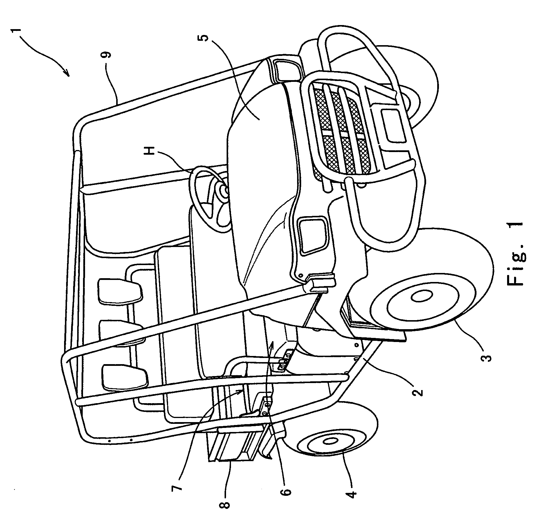
[0020]FIG. 1 is a perspective view of a utility vehicle 1 as viewed from front. As shown in FIG. 1, the utility vehicle 1 comprises a pair of front wheels 3 at right and left sides of a front part of a vehicle body 2 and a pair of rear wheels 4 at right and left sides of a rear part of the vehicle body 2. A hood 5 is mounted over the front wheels 3. Two bench-type seats, i.e., front and rear seats 6 and 7, are provided behind the hood 5, and are positioned in the vicinity of a center section in a longitudinal direction of the vehicle body 2. The front seat 6 includes a region where the driver is seated. A steering handle H is disposed in front of the region where the driver is seated. A cargo bed 8 is mounted behind the rear seat 7.

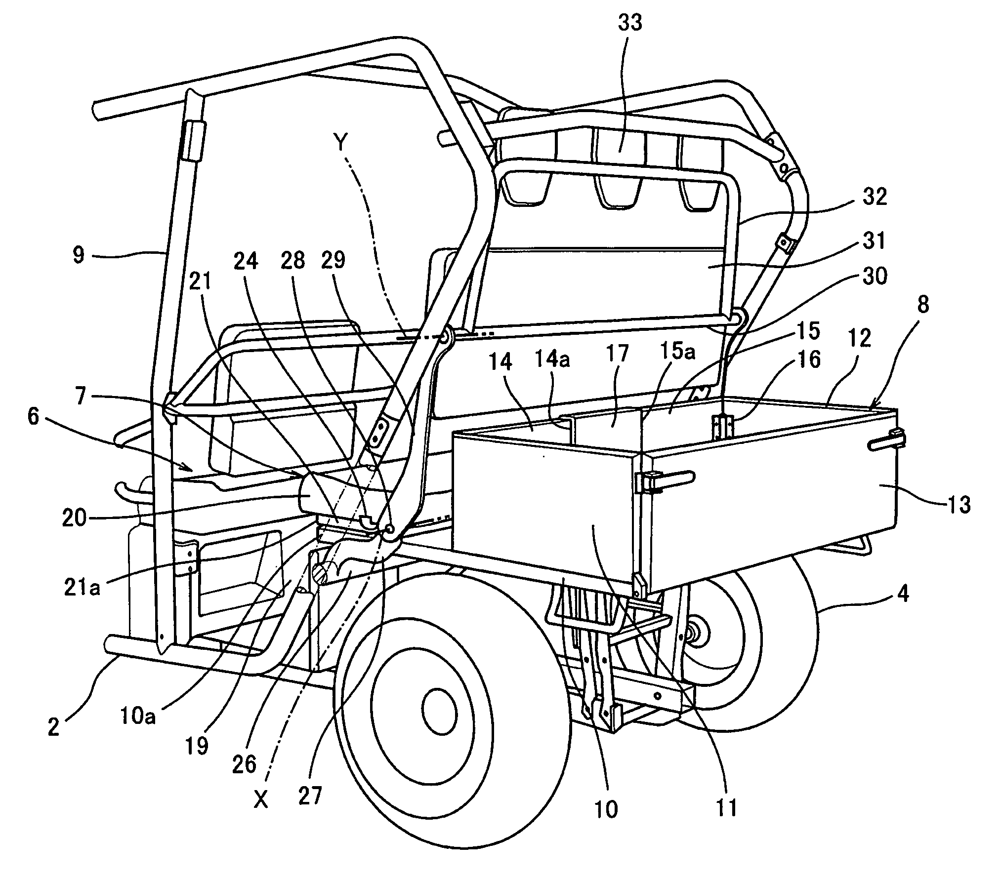
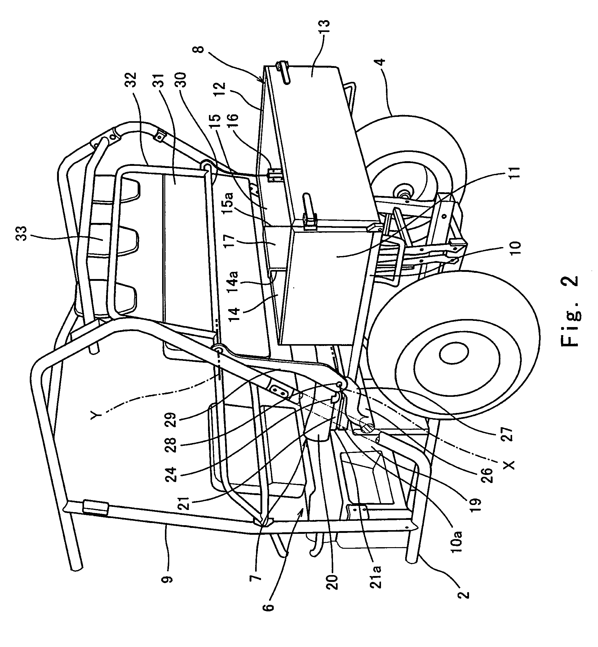
[0021]The cargo bed 8 extends rearward from a location near the rear seat 7 over the rear wheels 4. A cabin frame 9 extends from both sides of a front portion of the hood 5 to a region behind the rear seat 7. The cabin frame 9 surrounds a passenger space...

fourth embodiment

[0044]FIG. 14 is a rear view schematically showing main parts of a utility vehicle according to a In this embodiment, a first sprocket 60 is fixedly mounted on the pivot arm 29 so as to be located on an axis of the pivot 28. A shaft 62 is fixedly coupled to the rear seat backrest 31 so as to extend in the lateral direction. A second sprocket 61 is mounted on an end portion of the shaft 62. A chain 63 is installed around the first sprocket 60 and the second sprocket 61. In association with the pivot operation of the pivot arm 29, an angle formed between the pivot arm 29 and the rear seat backrest 31 is automatically changed. The chain 63 may be replaced by other suitable members such as a belt.

[0045]Whereas in the first to third embodiments, the bottom plate 21 is formed of the metal plate, it may be formed of a resin plate so long as it has stiffness. In addition, instead of the gate-shaped wall members 14 and 15, which are respectively protrusible forward from the front end portio...


PUM


Abstract

A utility vehicle comprises plural rows of seats mounted in a vehicle body of the utility vehicle, and an extendable cargo bed positioned behind the seats. The cargo bed includes a bottom wall member having an extended region which is extended forward relative to a cargo accommodating space in an unextended state of the cargo bed. The plural rows of seats include a rear seat having a rear seat seating portion which is rotatably provided on the extended region of the bottom wall member such that the rear seat seating portion is rotatable forward to an upright position. The rear seat seating portion has a bottom plate provided integrally with a bottom surface thereof. In a state where the rear seat seating portion is rotated forward and is in the upright position, the bottom plate of the rear seat seating portion defines a front wall member of the cargo bed.

Description

BACKGROUND ART[0001]A pick-up style utility vehicle typically includes a metal-made vehicle body, four wheels consisting of front wheels and rear wheels, an engine which is a driving source configured to generate a driving power, plural rows of seats on which passengers are seated, a cabin frame surrounding the seats from front and rear and from right and left, a cargo bed provided behind the seats, etc. In such a utility vehicle, it is desired that the cargo bed be required to have a large volume. However, the volume of the cargo bed is limited because the plural rows of seats occupy a space in a center section of the vehicle body. Accordingly, U.S. Pat. No. 6,905,159 discloses a utility vehicle in which two rows of seats are arranged and a rear seat is capable of being folded down forward so that a cargo bed is extendable in the resulting empty space.[0002]In order to extend the cargo bed in this utility vehicle, it is necessary to remove a screen shield serving as a front wall me...

Claims


Application Information

Patent Timeline
IPC IPC(8): B62D33/02B60N2/02
CPCB60N2/3031B60N2/305B62D47/003B60P3/423B60N2/36
Inventor TANAKA, SHUNJIICHIHARA, FUMIO
Owner KAWASAKI MOTORS LTD
Why Eureka
Try Eureka