Methods for driving electro-optic displays

a technology of electro-optic displays and displays, applied in the direction of electric digital data processing, instruments, computing, etc., can solve the problems of inadequate service life of these displays, preventing their widespread use, and gas-based electrophoretic media being susceptible to the same types of problems

Active Publication Date: 2009-10-15
E INK CORPORATION
View PDF86 Cites 77 Cited by
  • Summary
  • Abstract
  • Description
  • Claims
  • Application Information

AI Technical Summary

Problems solved by technology

Nevertheless, problems with the long-term image quality of these displays have prevented their widespread usage.
For example, particles that make up electrophoretic displays tend to settle, resulting in inadequate service-life for these displays.
Such gas-based electrophoretic media appear to be susceptible to the same types of problems due to particle settling as liquid-based electrophoretic media, when the media are used in an orientation which permits such settling, for example in a sign where the medium is disposed in a vertical plane.
Indeed, particle settling appears to be a more serious problem in gas-based electrophoretic media than in liquid-based ones, since the lower viscosity of gaseous suspending fluids as compared with liquid ones allows more rapid settling of the electrophoretic particles.
However, inevitably there is some error in writing images on an impulse-driven display.
Other types of mechanical non-uniformity may arise from inevitable variations between different manufacturing batches of medium, manufacturing tolerances and materials variations.(f) Voltage Errors; The actual impulse applied to a pixel will inevitably differ slightly from that theoretically applied because of unavoidable slight errors in the voltages delivered by drivers.
General grayscale image flow suffers from an “accumulation of errors” phenomenon.
This accumulation of errors phenomenon applies not only to errors due to temperature, but also to errors of all the types listed above.
As described in the aforementioned U.S. Pat. No. 7,012,600, compensating for such errors is possible, but only to a limited degree of precision.
For example, temperature errors can be compensated by using a temperature sensor and a lookup table, but the temperature sensor has a limited resolution and may read a temperature slightly different from that of the electro-optic medium.
Similarly, prior state dependence can be compensated by storing the prior states and using a multi-dimensional transition matrix, but controller memory limits the number of states that can be recorded and the size of the transition matrix that can be stored, placing a limit on the precision of this type of compensation.
In addition, many current display controllers can only make use of one updating scheme at any given time.
As a result, the display is not responsive enough to react to rapid user input, such as keyboard input or scrolling of a select bar.
This limits the applicability of the display for interactive applications.
However, in most of the aforementioned methods and controllers, the updating operation is “atomic” in the sense that once an update is started, the memory cannot accept any new image data until the update is complete.
This causes difficulties when it is desired to use the display for applications that accept user input, for example via a keyboard or similar data input device, since the controller is not responsive to user input while an update is being effected.
The method described in this paper uses structures already developed for gray scale image displays to reduce the unresponsive period by up to 65 percent, as compared with prior art methods and controllers, with only modest increases in the complexity and memory requirements of the controller.
None of the prior art described above provides a general solution to the problem of using multiple drive schemes simultaneously on a single display.
If the part of the display outside the selected area needs to be changed, the display must switch back to the slower full gray scale drive scheme, so that rapid updating of the selected area is not possible which the non-selected area is being changed.

Method used


Image

  • Methods for driving electro-optic displays
  • Methods for driving electro-optic displays
  • Methods for driving electro-optic displays

Examples


Embodiment Construction

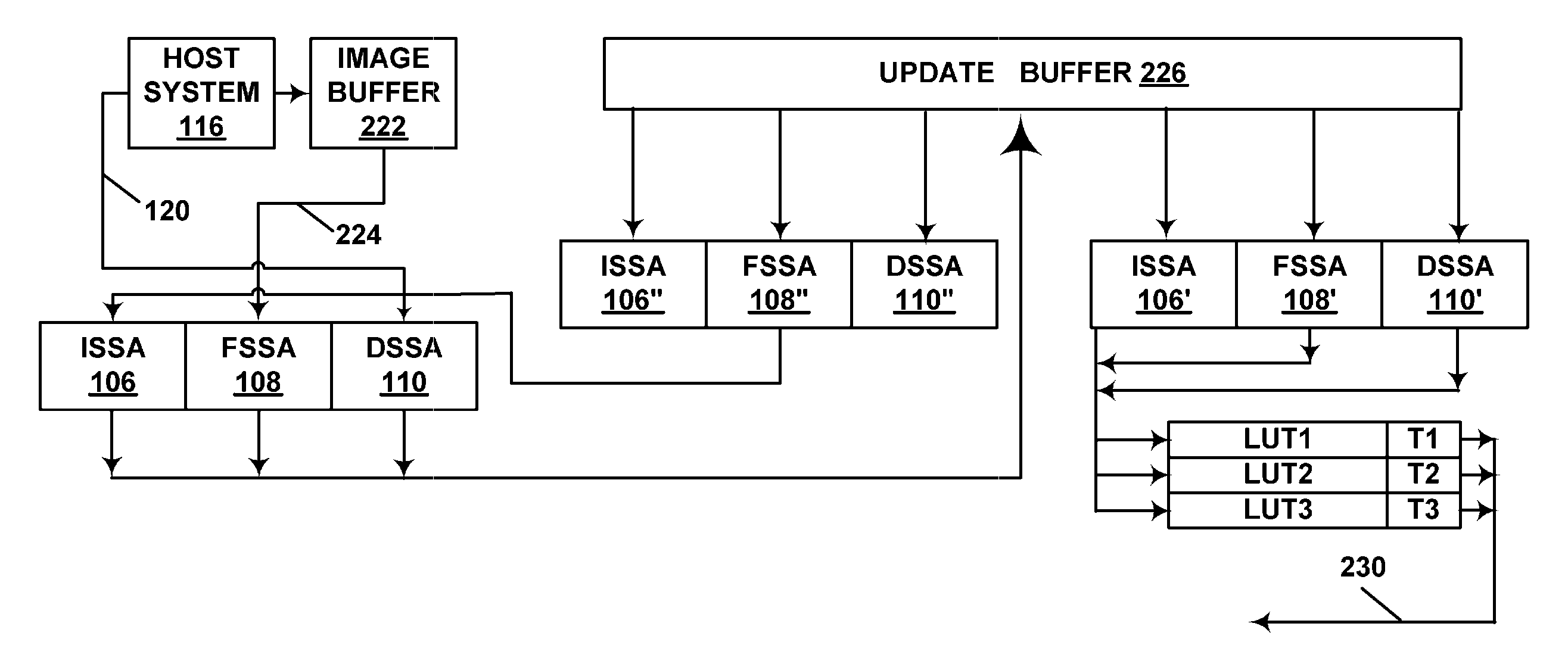
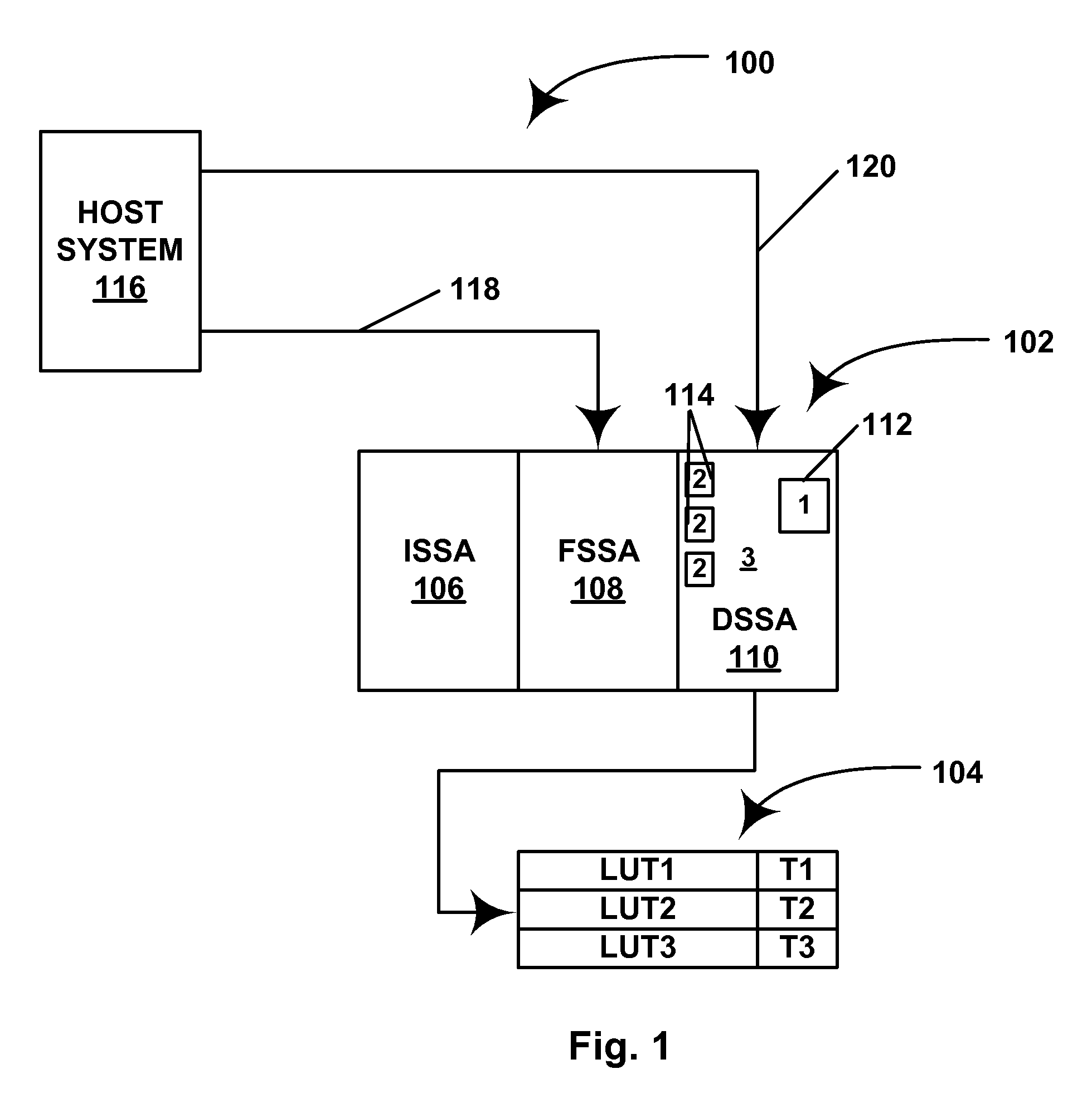
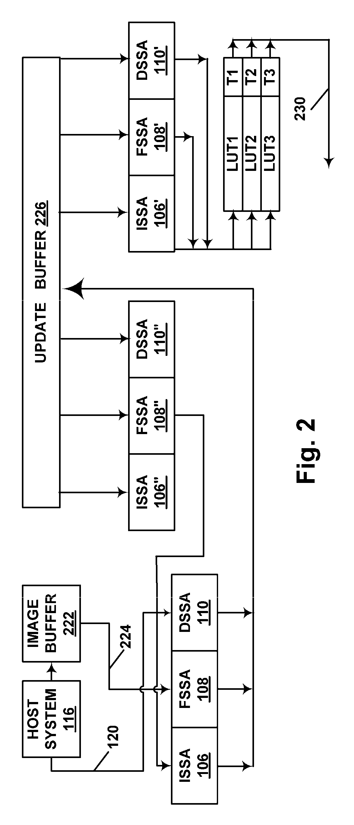
[0097]As indicated above, the present invention provides a data structure and method for operating a bistable electro-optic display. This data structure and method of operation allow for the simultaneous use of multiple drive schemes in the display. In preferred forms of the data structure and method of the present invention, the multiple drive schemes can begin at different times and thus run independently of each other.

[0098]The statement that the multiple drive schemes used in preferred forms of the present method can begin at different times does not imply that any given drive scheme can begin at any arbitrary time; commencement of the drive schemes is of course subject to certain limitations due to the manner in which the electro-optic display is driven. As discussed in the aforementioned MEDEOD applications, most high resolution displays use active matrix backplanes, with pixel electrodes arranged in a two-dimensional matrix defined by row electrodes and column electrodes. One...


PUM


Abstract

A data structure for use in controlling a bistable electro-optic display having a plurality of pixels comprises a pixel data storage area storing, for each pixel of the display, data representing initial and desired final states of the pixel, and a drive scheme index number representing the drive scheme to be applied; and a drive scheme storage area storing data representing at least all the drive schemes denoted by the drive scheme index numbers stored in the pixel data storage area. A corresponding method of driving a bistable electro-optic display using such a data structure is also provided.

Description

REFERENCE TO RELATED APPLICATIONS[0001]This application claims benefit of Application Ser. No. 61 / 044,067, filed Apr. 11, 2008.[0002]This application is related to:[0003](a) U.S. Pat. No. 6,504,524;[0004](b) U.S. Pat. No. 6,512,354;[0005](c) U.S. Pat. No. 6,531,997;[0006](d) U.S. Pat. No. 6,995,550;[0007](e) U.S. Pat. Nos. 7,012,600 and 7,312,794, and the related Patent Publications Nos. 2006 / 0139310 and 2006 / 0139311;[0008](f) U.S. Pat. No. 7,034,783;[0009](g) U.S. Pat. No. 7,119,772;[0010](h) U.S. Pat. No. 7,193,625;[0011](i) U.S. Pat. No. 7,259,744;[0012](j) U.S. Patent Publication No. 2005 / 0024353;[0013](k) U.S. Patent Publication No. 2005 / 0179642;[0014](l) U.S. Pat. No. 7,492,339;[0015](m) U.S. Pat. No. 7,327,511;[0016](n) U.S. Patent Publication No. 2005 / 0152018;[0017](o) U.S. Patent Publication No. 2005 / 0280626;[0018](p) U.S. Patent Publication No. 2006 / 0038772;[0019](q) U.S. Pat. No. 7,453,445;[0020](r) U.S. Patent Publication No. 2008 / 0024482;[0021](s) U.S. Patent Publicatio...

Claims


Application Information

Patent Timeline
Patent Type & Authority Applications(United States)
IPC IPC(8): G09G3/34
CPCG09G3/3433G09G2360/18G09G2360/16G09G3/344
Inventor OHKAMI, TAKAHIDEGATES, HOLLY G.
Owner E INK CORPORATION
Why Eureka
Try Eureka