Gain partitioning in a receiver

a receiver and gain technology, applied in the field of gain partitioning in the receiver, can solve the problems of degrading the signal-to-noise ratio, increasing the distortion products in the signal, and degrading the linearity performance of the system, so as to optimize the signal level entering

Active Publication Date: 2009-10-15
MAXLINEAR INC
View PDF6 Cites 7 Cited by
  • Summary
  • Abstract
  • Description
  • Claims
  • Application Information

AI Technical Summary

Benefits of technology

[0010]In accordance with the present invention, for a given receiver path gain defined, for example, by the product of the pre and post selectivity gains, the present invention provides a self-contained, compact apparatus and method for adjusting the partitioning between pre and post-selectivity gain to optimi

Problems solved by technology

The gain redistribution between amplifiers 110 and 140 reduces distortion but also results in degradation of the signal-to-noise (SNR) ratio.
Therefore a tradeoff exists between inc

Method used


Image

  • Gain partitioning in a receiver
  • Gain partitioning in a receiver
  • Gain partitioning in a receiver

Examples


Embodiment Construction

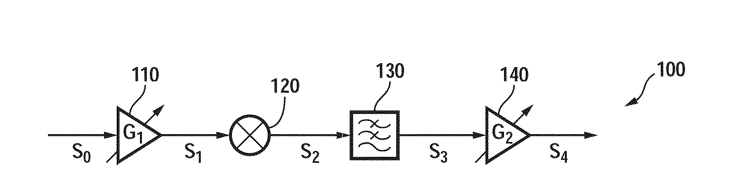
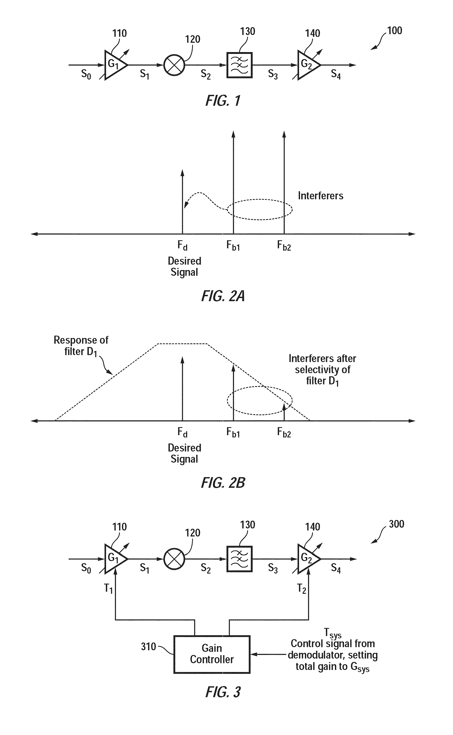
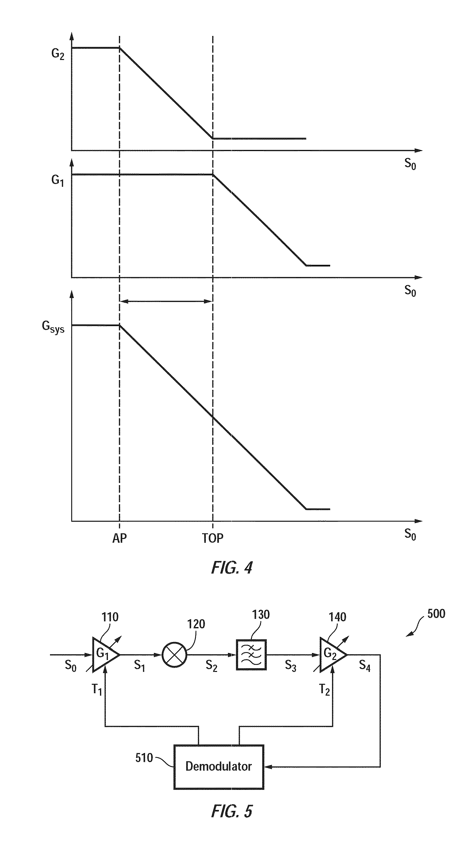
[0028]FIG. 6 is a block diagram of a receiver 600, in accordance with one embodiment of the present invention. Receiver 600 is shown as including, in part, amplifiers 110, 140, frequency converter 120, filter 130 and sensor 610. A local oscillator (not shown) provides an oscillating signal to frequency converter 120. Frequency converter 120 may be a mixer, a multiplier, etc. Demodulator 510 may be external or internal to receiver 600. Sensor 610 sense signal S1 to determine the strength of the RF signal. Signal S1 so sensed is supplied to demodulator / controller 510. Also supplied to demodulator / controller 510 is signal S4 that is generated by amplifier 140. In response, demodulator / controller 510 generates signals T1 and T2 that are respectively applied to amplifiers 110 and 140 to control their gains. As see from FIG. 6, receiver 600 together with demodulator / controller 510 form a pair of control loops L1 and L2, which are independently controlled by the demodulator / controller 510....


PUM


Abstract

An automatic gain control loop disposed in a receiver is adapted to compensate for varying levels of out of band interference sources by adaptively controlling the gain distribution throughout the receive signal path. One or more intermediate received signal strength indicator (RSSI) detectors are used to determine a corresponding intermediate signal level. The output of each RSSI detector is coupled to an associated comparator that compares the intermediate RSSI value against a corresponding threshold. The take over point (TOP) for gain stages is adjusted based in part on the comparator output values. The TOP for each of a plurality of gain stages may be adjusted in discrete steps or continuously.

Description

CROSS-REFERENCE TO RELATED APPLICATIONS[0001]The present application claims benefit under 35 USC 119(e) of U.S. provisional application No. 60 / 979,024, filed Oct. 10, 2007, entitled “A Technique For Optimizing Gain Partitioning In A Receiver”, the content of which is incorporated herein by reference in its entirety.BACKGROUND OF THE INVENTION[0002]A receiver system typically consists of a series of stages consisting of pre-selectivity gain and mixing, frequency selectivity (i.e. a filter) and post-selectivity gain and mixing. Conventional receivers either set a total system gain with a predetermined partition between pre- and post selectivity gain, or rely on a separate controller or demodulator to independently adjust pre and post selectivity gains to achieve the linearity / noise tradeoff.[0003]FIG. 1 is a simplified block diagram of a receiver 100, as known in the prior art. In receiver 100, amplifier 110 has a gain G1 that provides pre-selectivity gain. Frequency converter 120, wh...

Claims


Application Information

Patent Timeline
IPC IPC(8): H04B7/00
CPCH03G3/20H03G3/3068H04B17/318H04B1/16
Inventor LING, CURTISREDDY, MADHUKARWETHERELL, JOHN
Owner MAXLINEAR INC
Why Eureka
Try Eureka