Vertebral disc tensioning device

a technology of vertebral discs and tensioning devices, which is applied in the field of vertebral disc tensioning devices, can solve the problems of disc ultimately failing for cellular, slow disc degeneration in humans, and chronic back pain disorders and/or leg pain

Active Publication Date: 2009-10-15
MI4SPINE
View PDF2 Cites 81 Cited by
  • Summary
  • Abstract
  • Description
  • Claims
  • Application Information

AI Technical Summary

Problems solved by technology

Degeneration of discs in humans is typically a slow, complex process involving essentially all of the mechanical and physiologic components with loss of water holding capacity of the disc.
However, the disc ultimately fails for cellular reasons.
As a result of this loss of water, the disc space height may partially collapse, which may lead to chronic back pain disorders and / or leg pain as a result of the nerves being pinched.
This condition may lead to a number of problems.
Further, the ligaments and facets of the spine degenerate as well due to increased forces and stresses on these structures that occur as the disc loses its weight-bearing capacity.
These problems lead to a reduction in the foramenal height of the vertebrae, often causing central or lateral canal stenosis.
Because the nerve passes through the foramen, the nerve will often get pinched as the disc height decreases, leading to various types of back pain.
Further, these problems often lead to difficulty in walking.
The treatment of degenerative disc disease and associated spine ailments is one of the most costly medical conditions with an estimated annual direct cost in the United States of thirty-three billion dollars and a total annual societal cost exceeding one hundred billion dollars.
Indeed, in one's lifetime most individuals will experience an episode of significant back and / or neck pain.

Method used


Image

  • Vertebral disc tensioning device
  • Vertebral disc tensioning device
  • Vertebral disc tensioning device

Examples


Embodiment Construction

[0039]The following discussion of the embodiments of the invention directed to a vertebral disc tensioning device is merely exemplary in nature, and is in no way intended to limit the invention or its applications or uses.

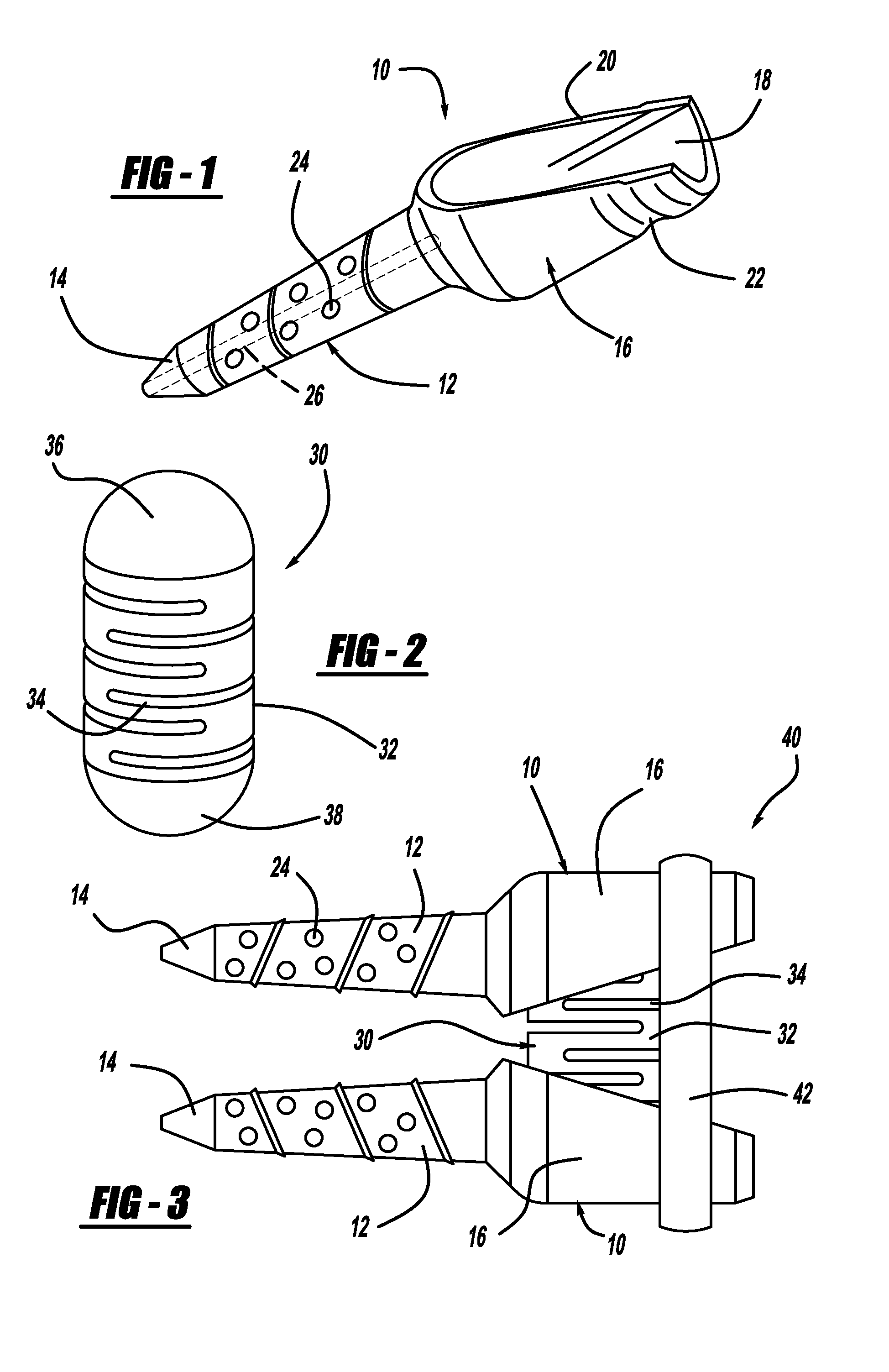
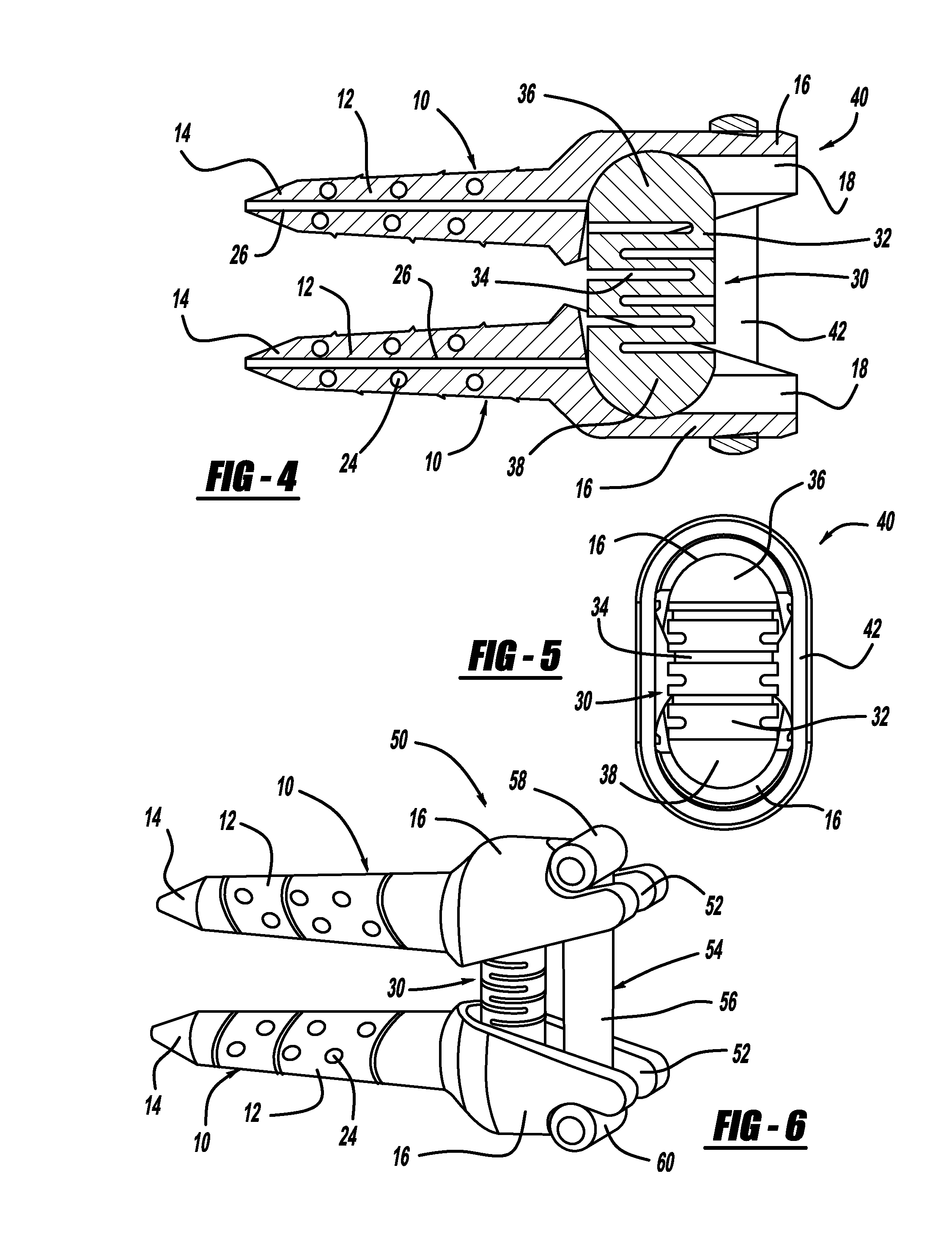
[0040]FIG. 1 is a perspective view of a pedicle screw 10 for use in a vertebral disc annular fibrosis tensioning and lengthening device (FIG. 3). The pedicle screw 10 includes a threaded and tapered body portion 12 having a tip 14. The body portion 12 includes a plurality of holes 24 that allow bone to grow therein when the screw 10 is threaded into the vertebral body so that the pedicle screw 10 is better anchored within the vertebra. The use of holes in the body portion of a pedicle screw to facilitate bone growth therein can be employed in other types of pedicle screws for other uses besides vertebral disc annular fibrosis tensioning and lengthening devices, such as spinal fusion pedicle screw and rod instrumentation, well known to those skilled in the art. The ...


PUM


Abstract

A vertebral disc tensioning device that restores the loss of disc height as a result of disc degeneration and other factors. The device includes first and second pedicle screws each including a screw body portion and a ball head. The device also includes first and second screw head portions each including an internal threaded bore where the first screw is inserted in the first screw head portion and is pivotally mounted relative thereto and the second screw is inserted in the second screw head portion and is pivotally mounted thereto. The device also includes a rigid connector that couples the first and second screw head portions where bolts are threaded through the connector and into the internal threaded bores of the first and second screw head portions. The device also includes a spring assembly offset from the rigid connector that applies a bias to separate the pedicle screws.

Description

CROSS-REFERENCE TO RELATED APPLICATIONS[0001]This application is a continuation-in-part application of U.S. patent application Ser. No. 11 / 646,750, filed Dec. 28, 2006, titled “Vertebral Disc Annular Fibrosis Tensioning and Lengthening Device.”BACKGROUND OF THE INVENTION[0002]1. Field of the Invention[0003]This invention relates generally to a vertebral disc tensioning device and, more particularly, to a vertebral disc tensioning device that includes a pair of pedicle screws, screw head portions coupled to each screw, a rigid connector connecting the screw head portions and a spring member applying a bias to gradually separate the pedicle screws to restore disc space height over time.[0004]2. Discussion of the Related Art[0005]The human spine includes a series of vertebrae interconnected by connective tissue referred to as intervertebral discs that act as a cushion between the vertebrae. The discs allow for movement of the vertebrae so that the spine can bend and rotate.[0006]The in...

Claims


Application Information

Patent Timeline
Patent Type & Authority Applications(United States)
IPC IPC(8): A61B17/70A61B17/86
CPCA61B17/7005A61B17/7007A61B17/701A61B2017/8655A61B17/7026A61B2017/00867A61B17/7025
Inventor PEREZ-CRUET, MIGUELANGELO J.PEPPER, JOHN R.
Owner MI4SPINE
Why Eureka
Try Eureka