Spinal implant and cutting tool preparation accessory for mounting the implant

a technology for spinal implants and cutting tools, applied in the field of spinal implants and surgical tools, can solve the problems of abnormal motions that become a source of pain, the effect of reducing the effectiveness over a period of time, and the compression of the disc, so as to facilitate the insertion of the implant, inhibit the expulsion of the implant, and promote bone fusion

Inactive Publication Date: 2007-01-11
WARSAW ORTHOPEDIC INC
View PDF102 Cites 46 Cited by
  • Summary
  • Abstract
  • Description
  • Claims
  • Application Information

AI Technical Summary

Benefits of technology

[0012] In another form of the present invention, an implant for insertion between a first vertebra having a first cortical bone endplate and a second vertebra having a second cortical bone endplate includes two terminal parts. The first terminal part defines a first bearing surface to bear against the first cortical bone endplate and a second bearing surface opposite the first surface to bear against the second cortical bone endplate. The second terminal part opposes the first terminal part and defines a third bearing surface to bear against the first cortical bone endplate and a fourth bearing surface opposite the third surface to bear against the second cortical bone endplate. The implant has an elongated central part defining an upper projection extending past the first and third surfaces, and a lower projection extending past the second and fourth surfaces. These projections correspondingly pass through openings in the first and second cortical bone endplates when the first and third surfaces bear against the first cortical bone endplate and the second and fourth surfaces bear against the second cortical bone endplate. The terminal parts are dimensioned to facilitate restoration of the natural geometry of the intervertebral space (lordosis, kyphosis, and parallel discs). Thus, the first and second surfaces may be separated by a first distance, and the third and fourth surface may be separated by a second distance greater than the first distance to accommodate a natural curvature of the spine.
[0014] According to another form, the bearing surfaces of the terminal end parts are defined by flanges extending from opposing ends of the implant along its longitudinal axis. Preferably, the bearing surfaces are generally flat for bearing against the cortical bone of the vertebral endplates of the two adjacent vertebrae. It is also preferred that openings be cut into the cortical endplates in their central regions corresponding to the length of a central part of the implant along the longitudinal axis and leaving a region of the cortical bone endplates around the periphery of the openings. The length of the remaining peripheral endplate corresponds to the length of the bearing surfaces along the longitudinal axis. When the implant is placed in position, the edges of the walls of the central part engage the openings cut in the cortical endplates and consequently do not substantially bear against the remaining peripheral portion of the endplates. A cavity may be defined by the central part that holds bone graft material in contact with the spongy bone of the two vertebrae. In contrast, the bearing surfaces of the flanges are disposed adjacent the edges of the openings of the cortical endplates and bear against the remaining portions of the endplates to establish a strong load-bearing relationship. Thus, both bone fusion and support are distinctly accommodated by different parts of the implant structure, which permits obtaining a satisfactory support of the vertebral bodies on the implant and an excellent arthrodesis.
[0016] In an additional form, a technique of spinal fixation includes cutting adjacent vertebrae and inserting an implant therebetween to promote fusion and provide suitable support. The implant may be inserted by anterior or posterior surgical approaches. The cutting may be performed by the cutting tool of the present invention and may include initially inserting the tool so that a first pair of faces are in contact with a respective one of the first and second cortical bone endplates, turning a handle to rotate the cutting portion to remove cortical bone with cutting teeth defined by a second pair of faces, and withdrawing the tool. The tool may be used to form openings readily positioned in the central region of the adjacent vertebrae leaving a portion of the cortical bone endplates about the openings. The insertion of the implant may include positioning the implant of the present invention between the first and second vertebrae and turning the implant about one quarter of a turn.

Problems solved by technology

It is known that when an intervertebral disc degenerates or is damaged, there is often a compression of the disc and a reduction in the normal intervertebral height.
Typically, this condition results in abnormal motions that become a source of pain.
However, one drawback of this proposal is its diminishing effectiveness over a period of time.
However, one drawback of these proposed implants is their lack of support of the cortical bone tissue, particularly bearing against the peripheral wall of the vertebral bodies.
This contributes to their diminishing effectiveness in maintaining normal disc height over a period of time.
As a result, the spinal implant must be neither engaged too far into the openings provided in the cortical endplates to provide a sufficiently dense load bearing surface, nor insufficiently inserted, in which case the bone fusion between the two vertebrae would be adversely affected by a poor anchorage.

Method used


Image

  • Spinal implant and cutting tool preparation accessory for mounting the implant
  • Spinal implant and cutting tool preparation accessory for mounting the implant
  • Spinal implant and cutting tool preparation accessory for mounting the implant

Examples


Embodiment Construction

[0037] For the purposes of promoting an understanding of the principles of the invention, reference will now be made to the embodiments illustrated herein and specific language will be used to describe the same. It will nevertheless be understood that no limitation of the scope of the invention is thereby intended. Any alterations and further modifications in the described processes, systems or devices, and any further applications of the principles of the invention as described herein, are contemplated as would normally occur to one skilled in the art to which the invention relates.

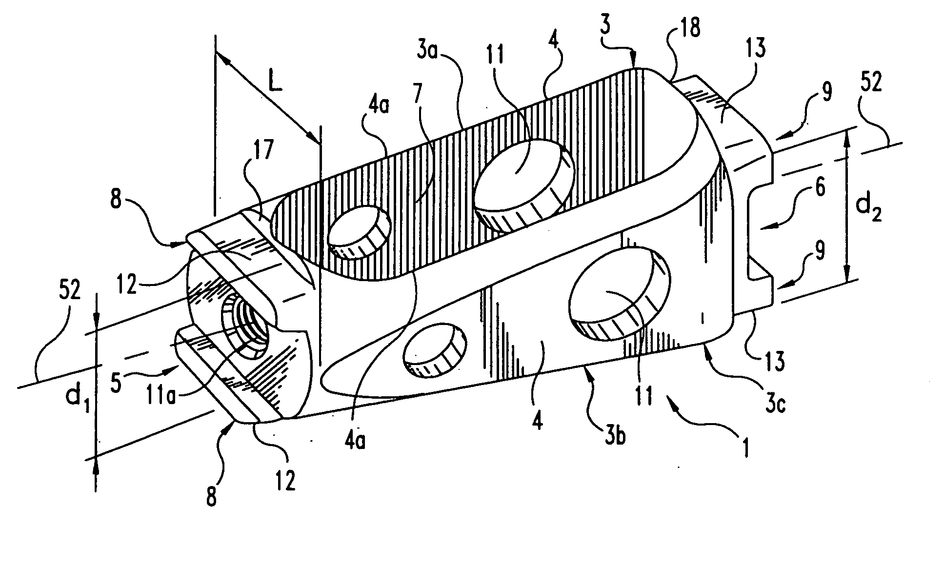
[0038]FIGS. 1, 6, and 7 depict spinal cage implant 1. Implant 1 is adapted to be inserted in a cavity provided in a damaged intervertebral disc 2 (FIG. 7), so as to restore the normal height of the intervertebral space between the two vertebrae V1 and V2 adjacent to the disc 2, for example, the lumbar vertebrae L3, L4 as depicted in FIG. 7. FIG. 1 shows implant 1 disposed along its longitudinal axis 52....


PUM

PropertyMeasurementUnit
heightaaaaaaaaaa
discal heightaaaaaaaaaa
shapeaaaaaaaaaa

Abstract

This invention relates to a spinal implant for promoting fusion of adjacent vertebrae and restoration of normal disc height. The spinal implant includes an upper and lower surface adapted to engage cancellous bone tissue in the vertebral bodies. The spinal implant also includes at least two opposing bearing surfaces adapted to bear against cortical bone tissue in the endplates of adjacent vertebrae. This invention also provides an instrumentation to prepare the intervertebral space to receive the spinal implant and techniques for treating patents in need of corrective spinal surgery.

Description

CROSS-REFERENCE TO RELATED APPLICATION [0001] The present application is a continuation of U.S. patent application Ser. No. 10 / 617,309, filed on Jul. 10, 2003; which is a divisional of U.S. patent application Ser. No. 09 / 420,622 filed on Oct. 19, 1999, and issued as U.S. Pat. No. 6,610,089; which is a continuation-in-part of PCT 625 Application Serial No. IB98 01 324 filed on Aug. 25 1998; which claims priority to French Patent Application Number 97 10664 filed on Aug. 26, 1997, all of which are hereby incorporated by reference in their entirety.FIELD OF THE INVENTION [0002] Generally, the present invention relates to spinal implant devices, surgical tools and associated techniques for promoting spinal fusion. BACKGROUND OF THE INVENTION [0003] It is known that when an intervertebral disc degenerates or is damaged, there is often a compression of the disc and a reduction in the normal intervertebral height. Typically, this condition results in abnormal motions that become a source o...

Claims


Application Information

Patent Timeline
Patent Type & Authority Applications(United States)
IPC IPC(8): A61F2/44A61F2/46A61B17/16A61B17/02A61F2/00A61F2/02A61F2/28A61F2/30
CPCA61B17/025A61F2310/00179A61B17/1757A61B2017/0256A61F2/28A61F2/442A61F2/4455A61F2/4465A61F2/447A61F2/4611A61F2002/2835A61F2002/30062A61F2002/30158A61F2002/30266A61F2002/30271A61F2002/30283A61F2002/30576A61F2002/30774A61F2002/30777A61F2002/30785A61F2002/30789A61F2002/30848A61F2002/4475A61F2002/448A61F2002/4623A61F2002/4627A61F2210/0004A61F2230/0026A61F2230/0063A61F2230/0082A61F2310/00017A61F2310/00023A61B17/1671A61F2002/3028A61F2002/30593A61F2002/30261A61F2002/30845A61F2/4603
Inventor LIU, MINGYANCHOPIN, DANIELMEISEL, HANS-JORG
Owner WARSAW ORTHOPEDIC INC
Why Eureka
Try Eureka