Field Focusing and Mapping in a Visual Prosthesis

a field focusing and mapping technology, applied in the field of electrode arrays, can solve the problems of noise applied to the stimulation electrode and achieve the effects of reducing the threshold of stimulation, reducing the noise applied, and improving the resolution

Inactive Publication Date: 2009-10-15
SECOND SIGHT MEDICAL PRODS +1
View PDF14 Cites 2 Cited by
  • Summary
  • Abstract
  • Description
  • Claims
  • Application Information

AI Technical Summary

Benefits of technology

[0007]The present invention is a system for mapping a high resolution image to a lower resolution electrode array and, by applying varying stimulus to neighboring electrodes, creating a perceived image greater in resolution than the electrode array. The invention is applicable to a wide range of neural stimulation devices including artificial vision and artificial hearing. By applying a sub-threshold stimulus to two neighboring electrodes where the sum of the stimuli is above the threshold of perception, a perception is created in neural tissue between the two electrodes. By adjusting the stimulus on neighboring electrodes, the location of stimulation can be altered. Further, noise can be applied to the stimulating electrode or its neighboring electrodes to reduce the threshold of stimulation.

Problems solved by technology

Further, noise can be applied to the stimulating electrode or its neighboring electrodes to reduce the threshold of stimulation.

Method used


Image

  • Field Focusing and Mapping in a Visual Prosthesis
  • Field Focusing and Mapping in a Visual Prosthesis

Examples


Embodiment Construction

[0012]The following description is of the best mode presently contemplated for carrying out the invention. This description is not to be taken in a limiting sense, but is made merely for the purpose of describing the general principles of the invention. The scope of the invention should be determined with reference to the claims.

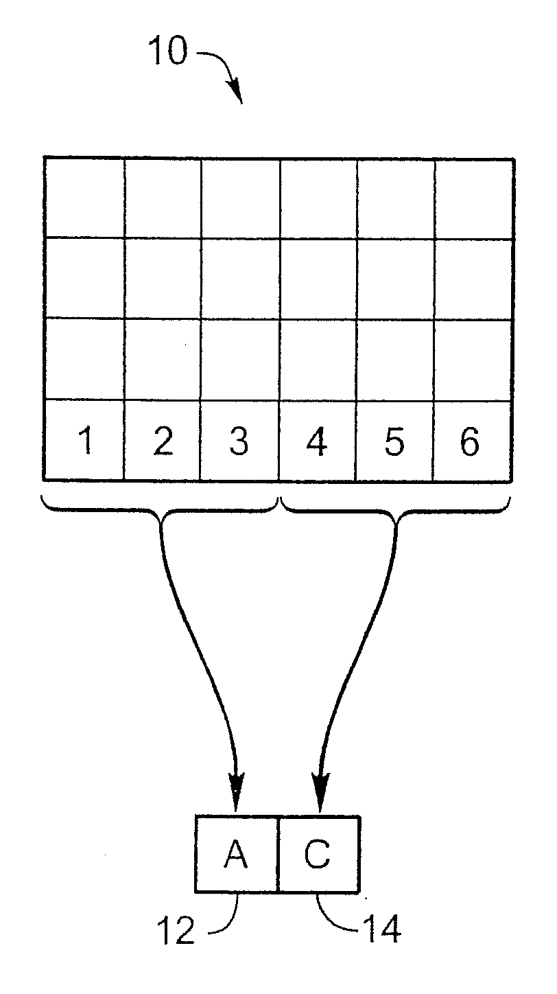
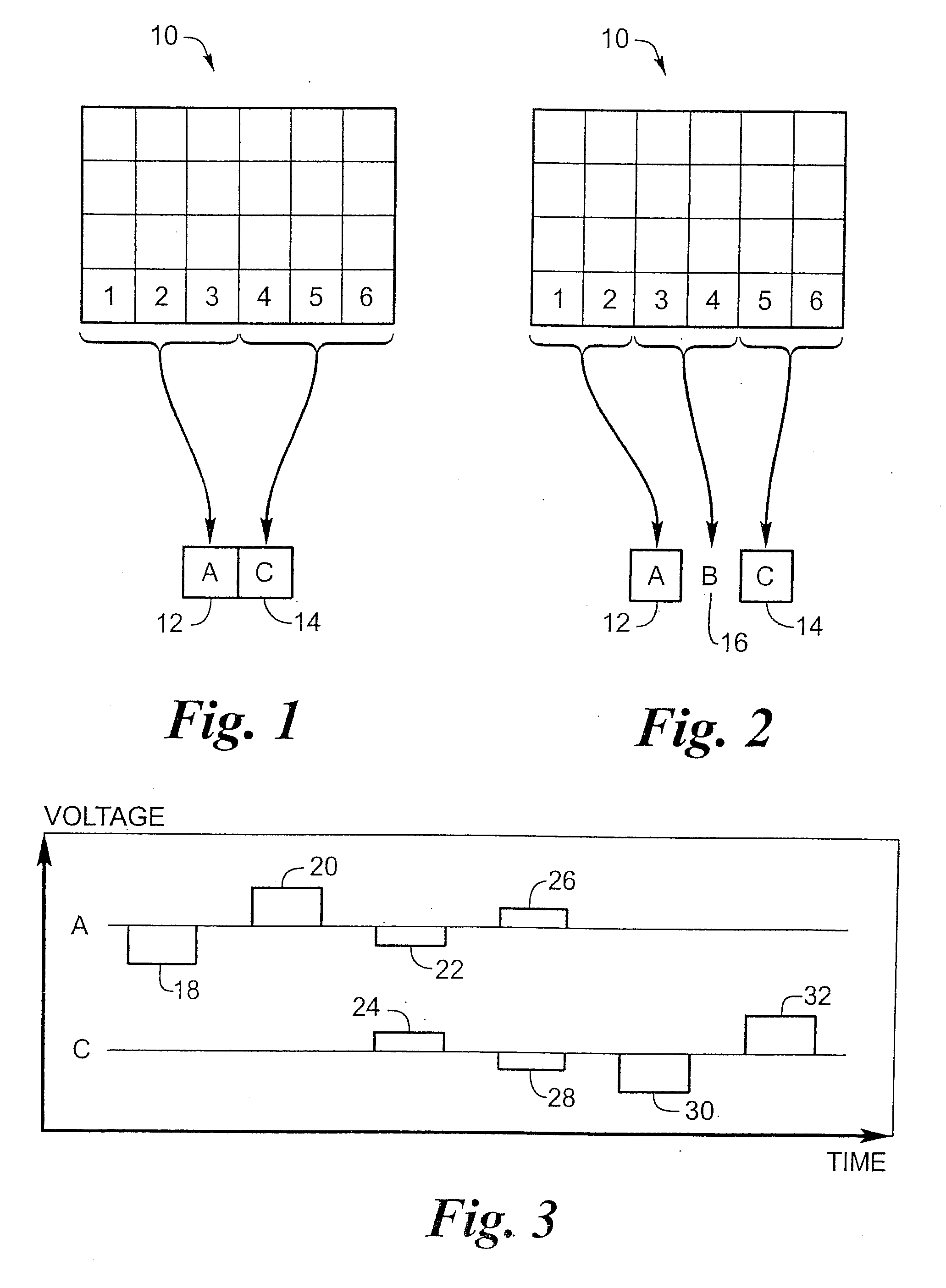
[0013]FIG. 1 shows the prior art. Using a visual prosthesis as an example, a 6 by 4 array of image pixels 10 is mapped to two electrodes, electrode A 12 and electrode C 14 which may be placed on the retinal surface or placed within the visual cortex. The left 12 pixels (columns 1-3) are mapped to electrode A 12 and the right 12 pixels (columns 4-6) are mapped to electrode C 14. The most common mapping is simply taking an average of the twelve pixels. Various modifications to a simple average are known which highlight edges, increase contrast, or otherwise make the limited information more relevant.

[0014]All neurons have a threshold potential that causes that...


PUM


Abstract

The present invention is a system for mapping a high resolution image to a lower resolution electrode array and, by applying varying stimulus to neighboring electrodes, creating a perceived image greater in resolution than the electrode array. The invention is applicable to a wide range of neural stimulation devices including artificial vision and artificial hearing. By applying a sub-threshold stimulus to two neighboring electrodes where the sum of the stimuli is above the threshold of perception, a perception is created in neural tissue between the two electrodes. By adjusting the stimulus on neighboring electrodes, the location of stimulation can be altered. Further, noise can be applied to the stimulating electrode or its neighboring electrodes to reduce the threshold of stimulation.

Description

CROSS REFERENCE TO RELATED APPLICATIONS[0001]This application is a divisional application of U.S. patent application Ser. 10 / 355,793, filed Jan. 31, 2003, for Field Focusing and Mapping in an Electrode Array. FIELD OF THE INVENTION[0002]The present invention is generally directed to electrode arrays, and more particularly to implantable electrode arrays for medical devices.BACKGROUND OF THE INVENTION[0003]Arrays of electrodes for neural stimulation are commonly used for a variety of purposes. Some examples include: U.S. Pat. No. 3,699,970 to Brindley and “The Sensations Produced by Electrical Stimulation of the Visual Cortex” by G. Brindley and W. Lewin, J. Physiol (London) 196:479-493:1968. Brindley's paper and patent describe an array of cortical electrodes for visual stimulation. One cortical electrode is used for each light percept. Each electrode is attached to a separate inductive coil for signal and power. U.S. Pat. No. 4,573,481 to Bullara describes a helical electrode to be...

Claims


Application Information

Patent Timeline
Patent Type & Authority Applications(United States)
IPC IPC(8): A61F9/08A61N1/36A61N1/05
CPCA61N1/36032A61N1/36185A61F9/08A61N1/36046
Inventor GREENBERG, ROBERT J.WILLIAMSON, RICHARD
Owner SECOND SIGHT MEDICAL PRODS
Why Eureka
Try Eureka