
Environmental monitoring and control system and method

a monitoring system and control system technology, applied in the direction separation processes, feed/discharge of sedimentation settling tanks, etc., can solve the problems of excessive environmental impact, inconvenient and costly on-site repair and replacement of components, and equipment must be reliable, so as to reduce the risk of overflow or damage

Inactive Publication Date: 2009-10-22
GODLIEN SCOTT +1
View PDF39 Cites 7 Cited by
  • Summary
  • Abstract
  • Description
  • Claims
  • Application Information

AI Technical Summary

Benefits of technology

[0014]The system may further comprise a processor for receiving volume data from the fluid compartment, and for initiating a preset adjustment scheme. The preset adjustment scheme may involve adjustment of the rate of fluid flow from the compartment; activation of an alarm; termination of a local fluid handling process; dumping of fluids into a storage tank and / or any other suitable step to prevent overflow or otherwise limit environmental damage.
[0017]In accordance with a third aspect of the invention, there is provided a method for preventing overflow of a fluid compartment continuous with a settling tank, the method comprising the steps of: placing a submersible pump within the fluid compartment, the submersible pump driven by a motor operatively attached to the pump by an impeller shaft such that the pump is operable by the motor without the motor being submerged within the compartment fluid; sensing fluid volume within the compartment; and adjusting pump operation based on sensed compartment fluid volume. The method may further comprise the step of communicating sensed fluid volume data to an operator.
[0020]The scheme may involve adjusting the amount of power to the motor; activation of an alarm; dumping of fluid from the compartment or from the settling tank; termination of a fluid handling process; and / or any other step to minimize risk of overflow or damage to the site.

Problems solved by technology

Moreover, equipment must be reliable as on-site repair and replacement of components is inconvenient and costly.
Further, equipment failure may cause excessive environmental impact if drilling fluids are spilled onto the site or otherwise make their way into nearby lakes and streams.
However, submersible pumps are prone to failure due to these very features.
A portable pump is not fixed in a permanent position, so it may be damaged during operation or transport.
Portable pumps require frequent maintenance due to worn seals and shafts, fluid entry into the motor causing motor failure, etc.
Further, as such pumps are constantly submerged in fluid during use, individual components may rust and fail.
Still further, in addition to poor reliability, the capacity of these pumps is limited by the small space typically available within the compartment.
Should one or both of the pumps fail, overflow of the clarified fluid compartment is likely.
When the clarified fluid compartment is continuous with a settling tank, backup of clarified fluid may cause overflow of the settling tank, depositing raw drilling fluid on the ground.
The spilled drilling fluid may contain chemicals or other additives that could be detrimental to soil, vegetation, and surface waters surrounding the site.

Method used


Image

  • Environmental monitoring and control system and method
  • Environmental monitoring and control system and method
  • Environmental monitoring and control system and method

Examples


Embodiment Construction

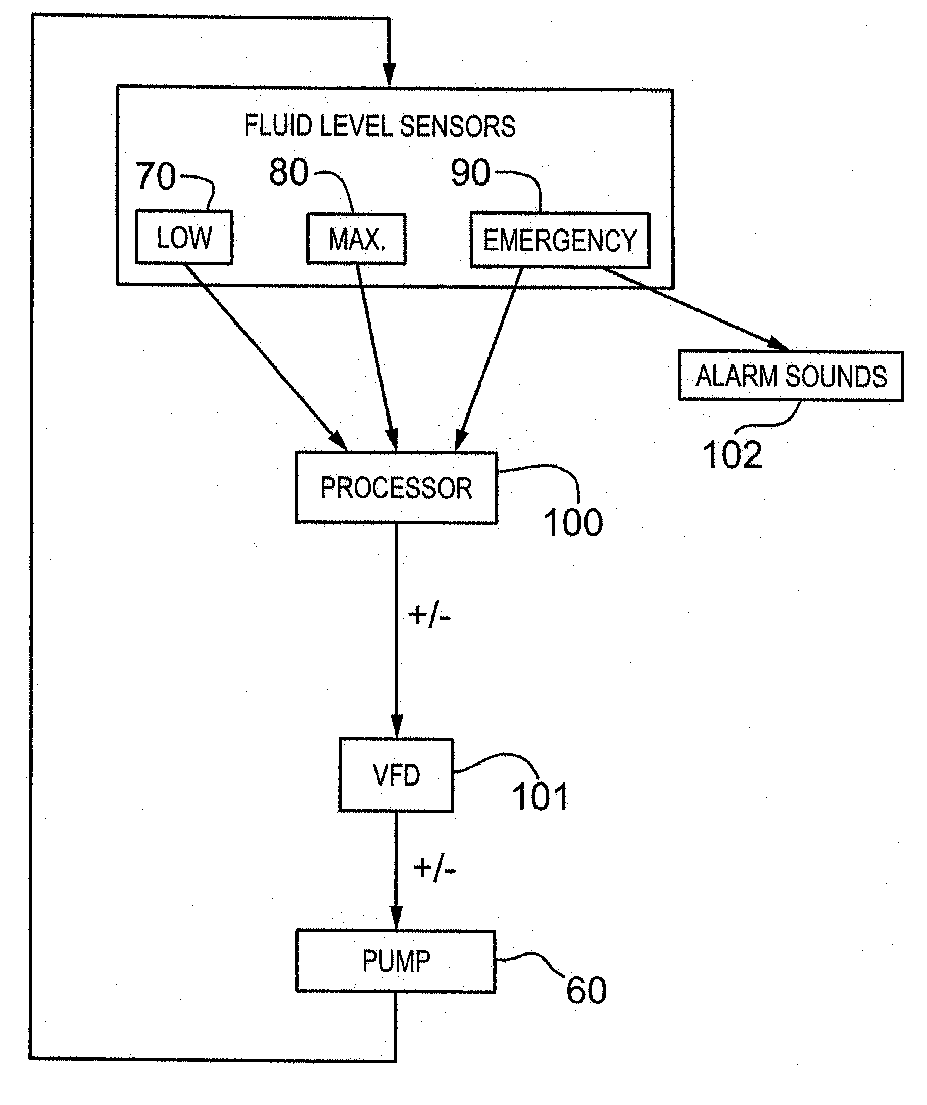
[0028]Generally, the present invention provides an environmental control system for a clarified fluid compartment. The clarified fluid compartment receives clarified fluid from a settling tank and clarified fluid is pumped from the compartment for storage or use of this recycled fluid.

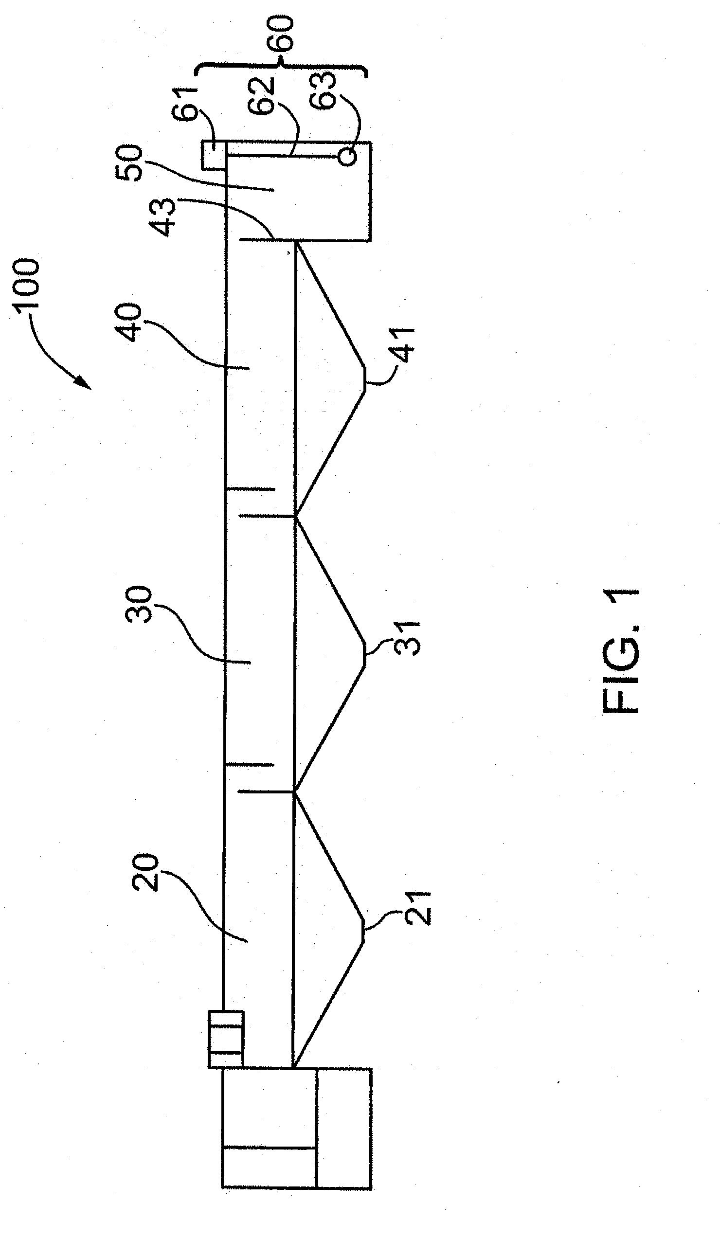
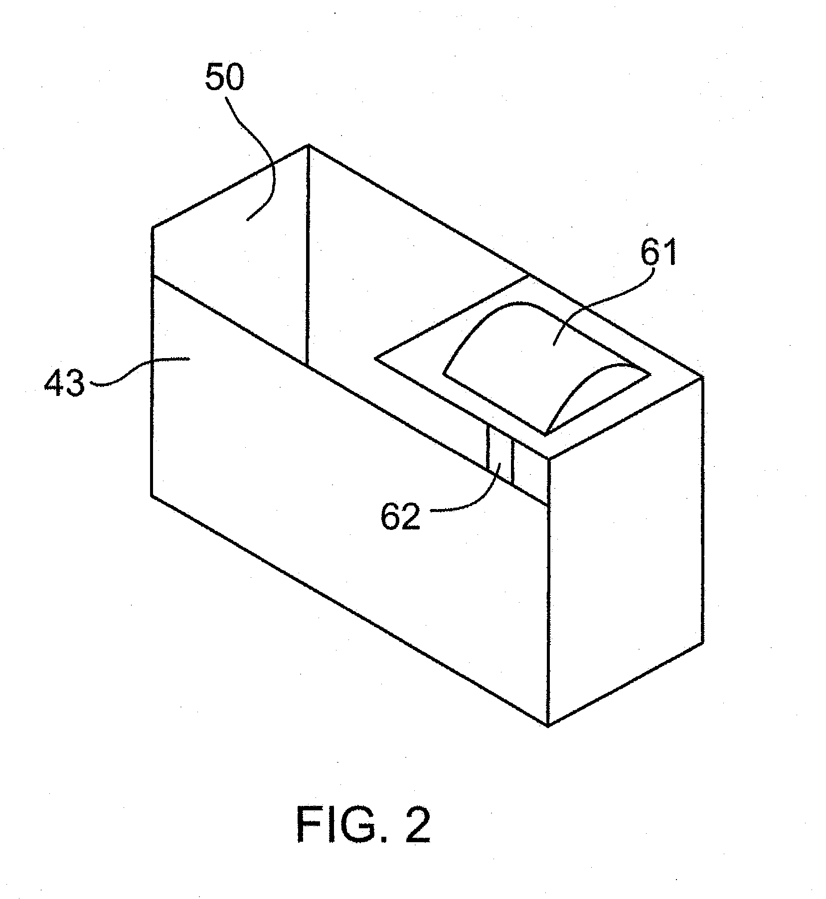
[0029]With reference to FIG. 1, a clarifying system 100 is shown in which a tank is divided into various compartments. Slurry feed enters the tank and passes through settling compartments 20, 30, and 40, to clarified fluid compartment 50. Solids fall from the slurry in each settling compartment 20, 30, and 40 and concentrate at the solids outlets 21, 31, and 41 of each respective compartment. Tank compartments 20, 30, 40, and 50 are separated from one another by weir and baffle systems such that fluid flows generally from tank compartment 20 to the clarified fluid tank 50. The number and size of settling compartments and clarified fluid compartments may be varied as necessary.

[0030]A clarifying system ...


PUM

PropertyMeasurementUnit
Poweraaaaaaaaaa
Flow rateaaaaaaaaaa
Volumeaaaaaaaaaa

Abstract

An environmental monitoring and control system and method are provided for preventing overflow of fluid from a compartment continuous with a settling tank. The system includes an improved pump configuration to minimize pump failure and maintenance, as well as monitoring of fluid volume within the compartment and adjustment of pumping rate as necessary to maintain an appropriate fluid volume. Operators on or off-site may be notified of compartment fluid volume to provide further redundancy.

Description

FIELD OF THE INVENTION[0001]The present invention relates generally to the handling of clarified drilling fluids. More particularly, the invention provides an environmental control system for reliable handling of clarified fluid at a drilling site.BACKGROUND OF THE INVENTION[0002]Downhole drilling operations are generally performed at remote locations, and it is therefore desirable to reuse or recycle as many resources as possible on-site and to minimize environmental impact. Moreover, equipment must be reliable as on-site repair and replacement of components is inconvenient and costly. Further, equipment failure may cause excessive environmental impact if drilling fluids are spilled onto the site or otherwise make their way into nearby lakes and streams.[0003]During clearwater drilling, fluid is pumped downhole through the drill string to the drill bit, and is returned to the surface as a slurry, carrying cuttings and suspended solids. The slurry is typically clarified on site by s...

Claims


Application Information

Patent Timeline
IPC IPC(8): B01D21/34B01D35/14B01D21/30B01D21/02
CPCE21B21/065B01D21/02
Inventor GODLIEN, SCOTTRUSSELL, GARY
Owner GODLIEN SCOTT
Learn More