Segment-core type stator for inner-rotor type rotary electric machines and an improved method for manufacturing the stator
Active Publication Date: 2009-10-22
DENSO CORP
View PDF6 Cites 12 Cited by
Summary
Abstract
Description
Claims
Application Information
AI Technical Summary
This helps you quickly interpret patents by identifying the three key elements:
Problems solved by technology
Method used
Benefits of technology
Benefits of technology
[0019]With this configuration, the difficulty in fitting the segment cores to the stator coil can be eliminated, while the number of divisions of the stator core can be reduced. Therefore, the rigidity of the stator can be enhanced, and the durability can also be enhanced against magnetic noise and external impacts. In addition, this configuration can contribute to simplification of the processes for manufacturing the stator. Further, since the magnetic resistance of the stator core can be reduced, the efficiency, in turn, can be enhanced, leading to the increase of the output and the torque.
[0021]Thus, magnetic resistance can be further reduced, and thus, local increase of the magnetic resistance can be reduced. Accordingly, magnetic vibration and magnetic noise can also be reduced.
[0023]Thus, magnetic resistance can be further reduced, and thus, local increase of the magnetic resistance can be reduced. Accordingly, magnetic vibration and magnetic noise can also be reduced.
Problems solved by technology
However, such a large-size flat wire cannot be wound about a stator with the use of a coil winder, unlike the case of winding a normal fine round wire.
On the contrary, bending, per se, has been difficult in winding such a large-size flat wire.
For this reason, the stator coil cannot be easily inserted into a cylindrical stator core.
Therefore, it will be very difficult to position the slot-accommodated portions, as they are, radially inside the stator core having a relatively small inner diameter.
However, the larger the number of divisions is, the smaller each of the segment cores may become.
This, in turn, may complicate the process of mechanically connecting a number of segment cores, each having slots into which the slot-accommodated portions have been inserted.
However, the large number of segment cores with a large number of mechanical connecting portions may unavoidably deteriorate the mechanical rigidity of the stator core.
In addition, the large number of segment cores may necessitate the increase of the magnetic resistance of the stator core, leading to deterioration in the output and the torque.
On the other hand, a segment-core type stator having a less number of divisions, such as two, may make it difficult for a cage stator coil with a relatively large diameter, to be inserted into the slots in the segment cores.
Method used
Image
Click on the blue label to locate the original text in one second.
Reading with bidirectional positioning of images and text.
Examples
first embodiment
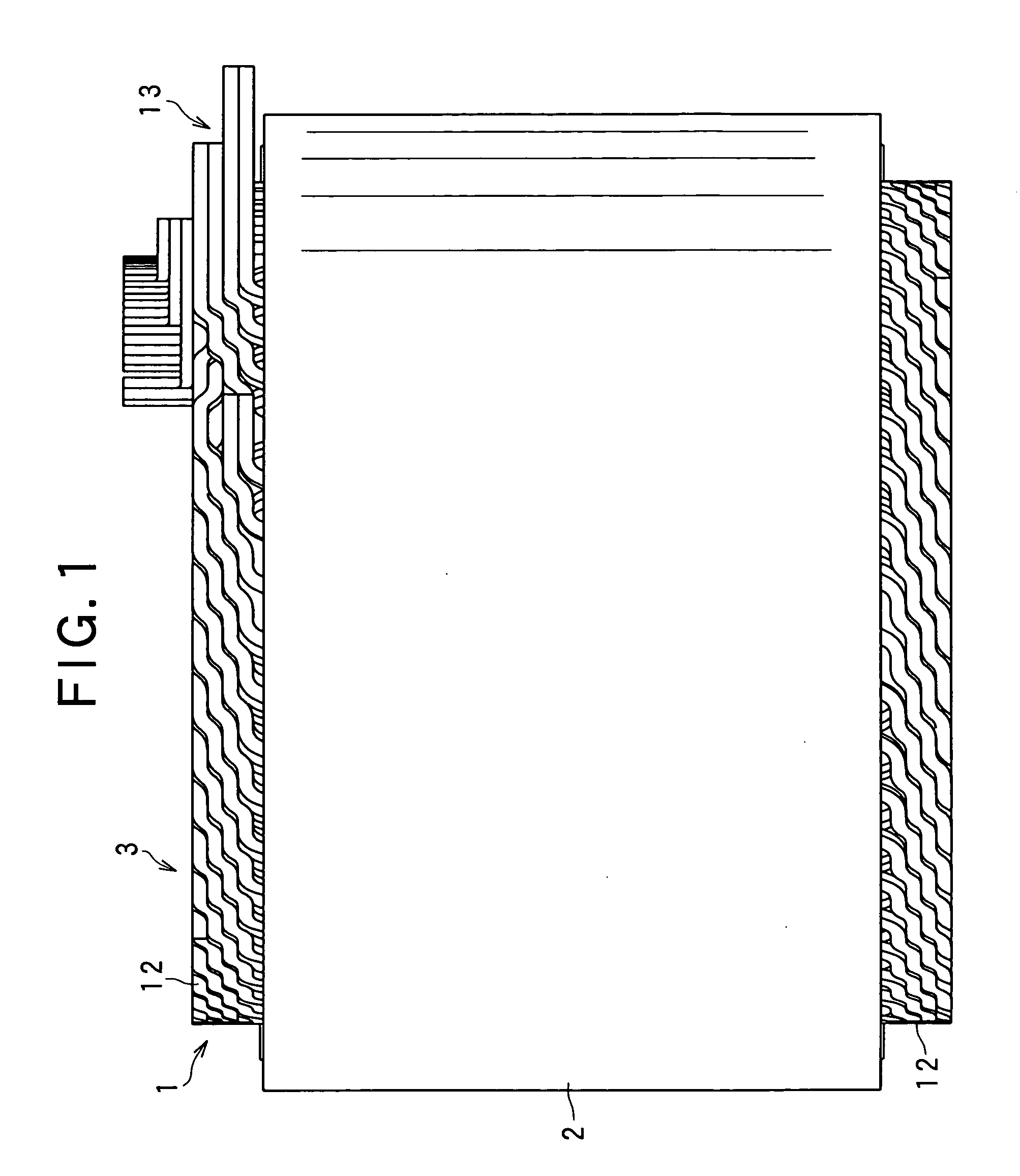
[0043]Referring to a side view shown in FIG. 1, an example of a stator structure is described.
[0044]FIG. 1 shows a stator 3 for a radially-gaped inner-rotor type rotary electric machine. The stator 3 includes a stator coil 1, a stator core 2 into which the stator coil 1 is fitted.
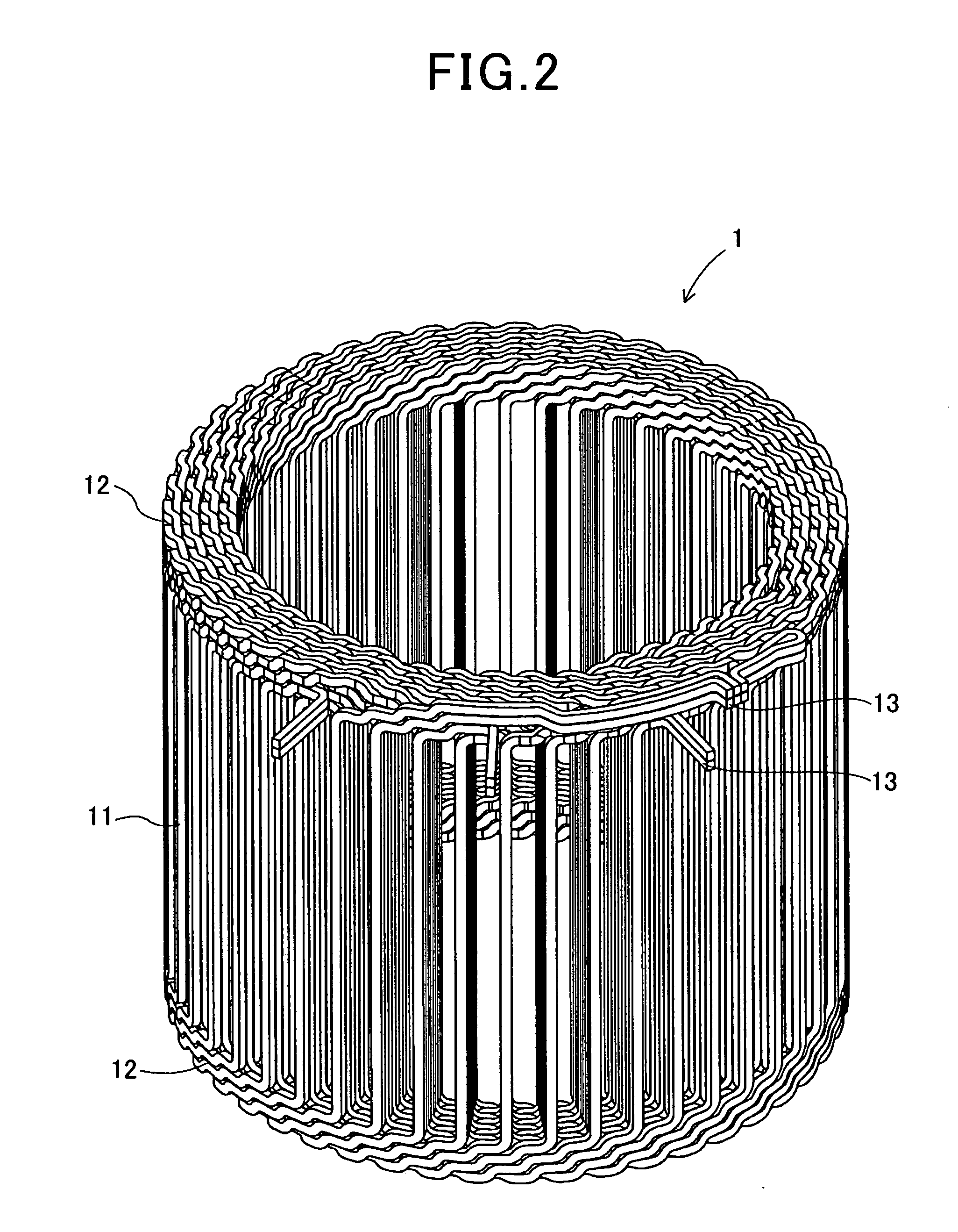
[0045]The stator coil 1 is configured by star-connecting three-phase windings, each of which is obtained by winding in a distributed manner a large-size flat conductor wire having a large cross-sectional area. Thus, the stator coil 1, as a whole, has the shape of a cage.
[0046]The stator coil 1 includes a number of slot-accommodated portions 11 which are conductive parts to be inserted into respective slots of the stator core 2. The stator coil 1 also includes coil end portions 12 which are conductive parts projected axially outward from both ends of the respective slot-accommodated portions, or in other words, projected from both end faces of the stator core 2. In FIG. 1, the slot-accommodated portions are ...
first modification
(First Modification)
[0071]Preferably, the circumferential positions of the mutually bonded faces of the half-cylindrical segment cores 4, 4 for configuring each of the end cores 21, 22 may be circumferentially offset from the circumferential positions of the mutually bonded faces of the arc segment cores 5 for configuring the center core 23. Thus, magnetic resistance can be reduced.
second modification
(Second Modification)
[0072]In the above embodiment, the intermediate cores 21′, 22′ have been arranged between the end cores 21, 22 and the center core 23, and each of the intermediate cores 21′, 22′ has been configured by the half-cylindrical segment cores 4, 4, similar to the end cores 21, 22. In this case as well, it is preferable that the circumferential positions of the mutually bonded faces of the half-cylindrical segment cores 4, 4 for configuring each of the end cores 21, 22 may be circumferentially offset from the circumferential positions of the mutually bonded faces of the half-cylindrical segment cores 4, 4 for configuring each of the intermediate cores 21′, 22′. Thus, magnetic resistance can be decreased.
PUM
Property
Measurement
Unit
Angle
aaaaa
aaaaa
Diameter
aaaaa
aaaaa
Abstract
When accommodating a cage stator coil in a stator core made up of distributed cores, an end side distributed core composing end side core at an end side in axial direction is made larger than a central side distributed core composing central side core. The cage stator coil is formed by compressing a central portion of an original cage stator coil. The end side segment core composing the end core is set at a central portion in an axial direction of the cage stator coil then the end side coil is moved to an end portion in the axial direction. The central side segment core composing the central core is set at the central portion in the axial direction of the cage stator coil thereafter.
Description
CROSS-REFERENCE TO RELATED APPLICATION[0001]This application is based on and claims the benefit of priority from earlier Japanese Patent Application No. 2008-110784 filed Apr. 21, 2008, the description of which is incorporated herein by reference.BACKGROUND OF THE INVENTION[0002]1. Technical Field of the Invention[0003]The present invention relates to a segment-core type stator for radially-gapped inner-rotor type rotary electric machines and a method for manufacturing the stator.[0004]2. Related Art[0005]Recently, it is essential for the automotive industry to give serious consideration to the environment and power saving. Under such circumstances, EVs (electric vehicles) and HVs (hybrid vehicles) have been researched and put to practical use.[0006]In vehicles, such as EVs and HVs, it is important to reduce vehicle weight that has strong positive correlation with fuel consumption. In this regard, there has been a strong demand for enhancing output per unit weight (kW / kgw) of a high...
Claims
Application Information
Patent Timeline
Application Date:The date an application was filed.
Publication Date:The date a patent or application was officially published.
First Publication Date:The earliest publication date of a patent with the same application number.
Issue Date:Publication date of the patent grant document.
PCT Entry Date:The Entry date of PCT National Phase.
Estimated Expiry Date:The statutory expiry date of a patent right according to the Patent Law, and it is the longest term of protection that the patent right can achieve without the termination of the patent right due to other reasons(Term extension factor has been taken into account ).
Invalid Date:Actual expiry date is based on effective date or publication date of legal transaction data of invalid patent.

