Detection of the state of the elements of an electric branch comprising a load and a switch

Active Publication Date: 2009-10-22
STMICROELECTRONICS (TOURS) SAS
View PDF23 Cites 4 Cited by
  • Summary
  • Abstract
  • Description
  • Claims
  • Application Information

AI Technical Summary

Benefits of technology

[0006]The present invention aims at overcoming al

Problems solved by technology

This circuit however does not enable distinguishing all the possible states of the circuit components (load and switches).

Method used


Image

  • Detection of the state of the elements of an electric branch comprising a load and a switch
  • Detection of the state of the elements of an electric branch comprising a load and a switch
  • Detection of the state of the elements of an electric branch comprising a load and a switch

Examples


Embodiment Construction

[0030]The same elements have been designated with the same reference numerals in the different drawings.

[0031]For clarity, only those steps and elements which are useful to the understanding of the present invention have been shown and will be described. In particular, the nature of the load(s) present in the circuit will not be detailed, since any type of load can be monitored by a circuit according to an embodiment of the present invention, provided, if the protection element is placed in parallel with the load, that the load has a low impedance with respect to this protection element.

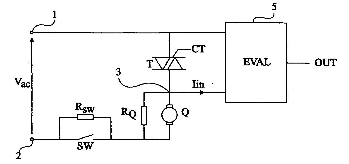
[0032]FIG. 1 illustrates a circuit for detecting the state of a load and of two switches which control it. This circuit comprises a load Q in series with two switches T and SW between two terminals 1 and 2 of application of an A.C. voltage Vac. Switch T is, for example, a triac controlled by a control signal CT of a programmer (not shown), for example, that of a washing machine. In the case of a wash...


PUM


Abstract

A method for detecting the state of at least one element of a circuit comprising one or several loads, powered by an A.C. voltage and in series with at least one first switch. The state of the element is obtained by analyzing, at several times in a period of the A.C. voltage, the amplitude of a current sampled from the junction point of the load and of the first switch.

Description

BACKGROUND OF THE INVENTION[0001]1. Field of the Invention[0002]The present invention generally relates to the detection of the state of a load powered by an A.C. power supply and, more specifically, to the monitoring of the state of this load and of one or several switches which control it.[0003]The present invention more specifically applies to the detection of possible failures of the load and of the switch(es) in series with this load.[0004]2. Discussion of the Related Art[0005]Many circuits and methods for detecting the failure of a load have been provided. For example, US patent application No 2006 / 0043944 provides studying the voltage across the load and comparing it with thresholds. This circuit however does not enable distinguishing all the possible states of the circuit components (load and switches).SUMMARY OF THE INVENTION[0006]The present invention aims at overcoming all or part of the inadequacies of known techniques.[0007]An embodiment of the present invention aims at...

Claims


Application Information

Patent Timeline
IPC IPC(8): G01R19/00
CPCG01R19/16538G01R31/2825G01R31/2843Y04S40/12H02J13/0017Y02B90/2607H01H9/167H02J13/00036H02J13/00006Y02B90/20Y04S10/18Y02E60/00G01R27/00G01R31/50
Inventor BENABDELAZIZ, GHAFOURPAILLET, PASCAL
Owner STMICROELECTRONICS (TOURS) SAS
Why Eureka
Try Eureka