Low-height, low-cost, high-gain antenna and system for mobile platforms

a high-gain, low-height technology, applied in the direction of individual energised antenna arrays, linear waveguide fed arrays, wireless commuication services, etc., can solve the problems of low cost, high cost, complexity and height of antennas, and the weight of various waveguide antennas, etc., to achieve the effect of low cost, low cost and low cos

Inactive Publication Date: 2004-06-15
ASTRONICS AEROSAT CORP
View PDF58 Cites 41 Cited by
  • Summary
  • Abstract
  • Description
  • Claims
  • Application Information

AI Technical Summary

Benefits of technology

According to one embodiment of the present invention, a leaky waveguide antenna array that receives and / or transmits electromagnetic signals, includes a plurality of radiation waveguides disposed in parallel to each other to form the antenna array. A feed waveguide provides an electromagnetic signal to the plurality of radiation waveguides and / or receives a plurality of electromagnetic signals from the plurality of radiation waveguides and provides a composite electromagnetic signal at an output of the feed waveguide. Each of the plurality of radiation waveguides has a waveguide axis and includes a plurality of apertures arranged in a direction of the waveguide axis. The feed waveguide includes a first section of waveguide having a first end connected to an input / output port. The first section of waveguide has a height substantially the same as the height of each of the plurality of radiation waveguides and the first section of waveguide has a second end coupled to a first junction point. The first junction point transitions from the first section of waveguide to a second section of waveguide and a third section of waveguide that each have a height that is substantially half of the height of the first section of waveguide. The second section of waveguide transitions with an upward ramp to the substantially half height of the first section of waveguide. The third section of waveguide transitions with a downward sloping ramp to the substantially half height of the first section of waveguide. The third section of waveguide is substantially a mirror image of the second section of waveguide. The feed waveguide also includes a septum connected to vertical walls of the first, second and third sections of waveguide which aids in the transition from the height of the first section of the waveguide to the height of the second section and the third section of waveguide. Each of the second section of waveguide and the third section of waveguide are coupled to a corresponding first signal port and second signal port of the feed waveguide. Each of the first signal port and the second signal port are coupled to a corresponding one of the plurality of radiation waveguides.
With this arrangement, an antenna of reduced height and length can be constructed and mounted on a moving platform such as, for example, an automobile and that is part of a system to transmit and / or receive any of live video programming, images, interactive services, two-way communications and other data signals. In addition, the leaky waveguide antenna array and feed waveguide can be construed or molded from a composite material. With this arrangement, the antenna and feed waveguide can be manufactured more easily, reduced in weight as compared to, for example, an antenna assembled out of a metal such as aluminum, and can be provided at a lower cost.

Problems solved by technology

However, the tracking mechanism can constitute a considerable part of the whole antenna manufacturing costs, complexity and height or mounting area of the antenna.
Another issue with the various slotted waveguide antennas that have been proposed are the costs, the ease of manufacture, and the weight of the various waveguide antennas.
However, such a manufacturing process may not be suitable for mass production and therefore such a slotted waveguide antenna array may not be provided inexpensively using such a method.
Thus, conventional slotted waveguide antenna arrays are typically bulky, heavy and not suitable for efficient and cost effective mass production.

Method used


Image

  • Low-height, low-cost, high-gain antenna and system for mobile platforms
  • Low-height, low-cost, high-gain antenna and system for mobile platforms
  • Low-height, low-cost, high-gain antenna and system for mobile platforms

Examples


Embodiment Construction

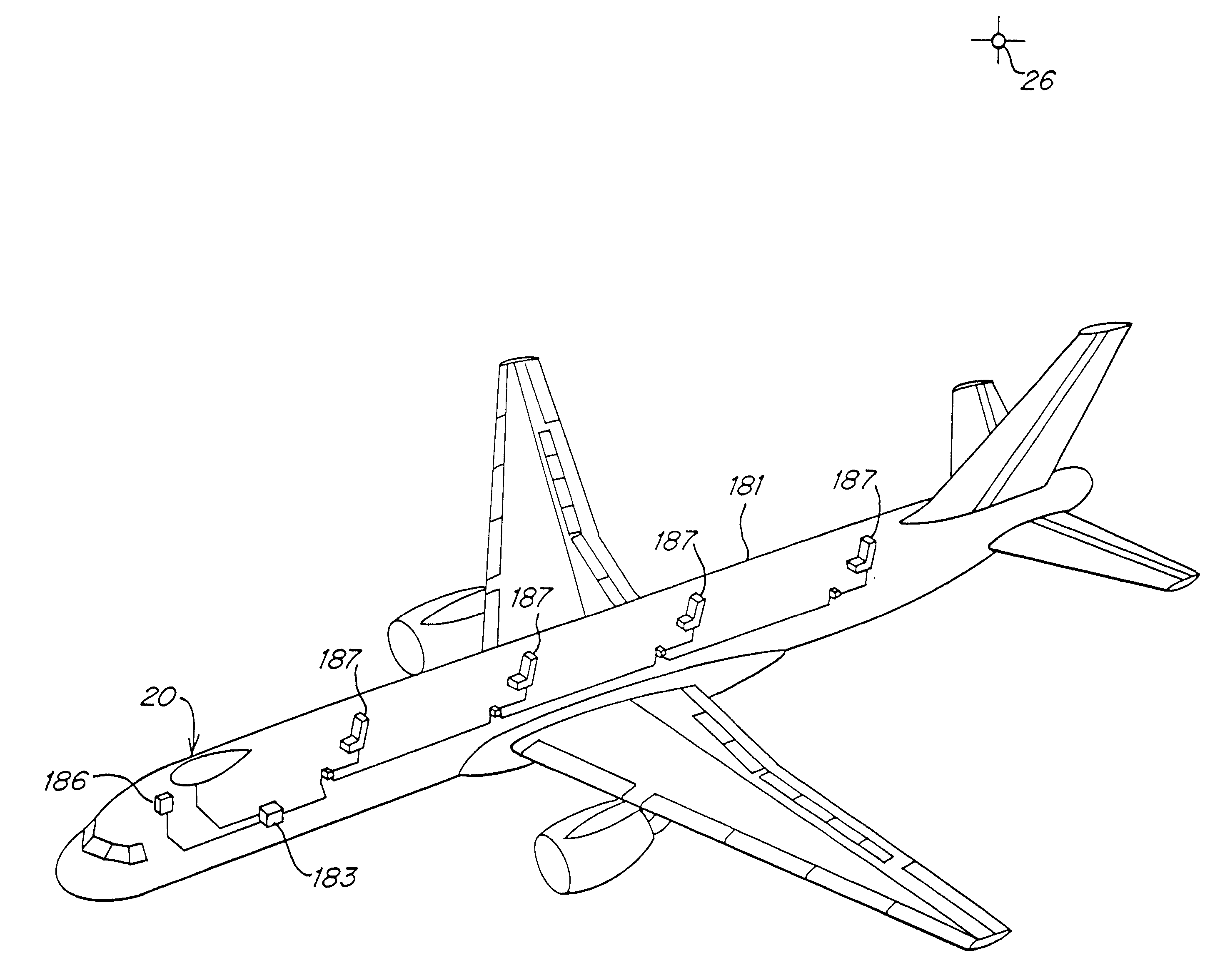
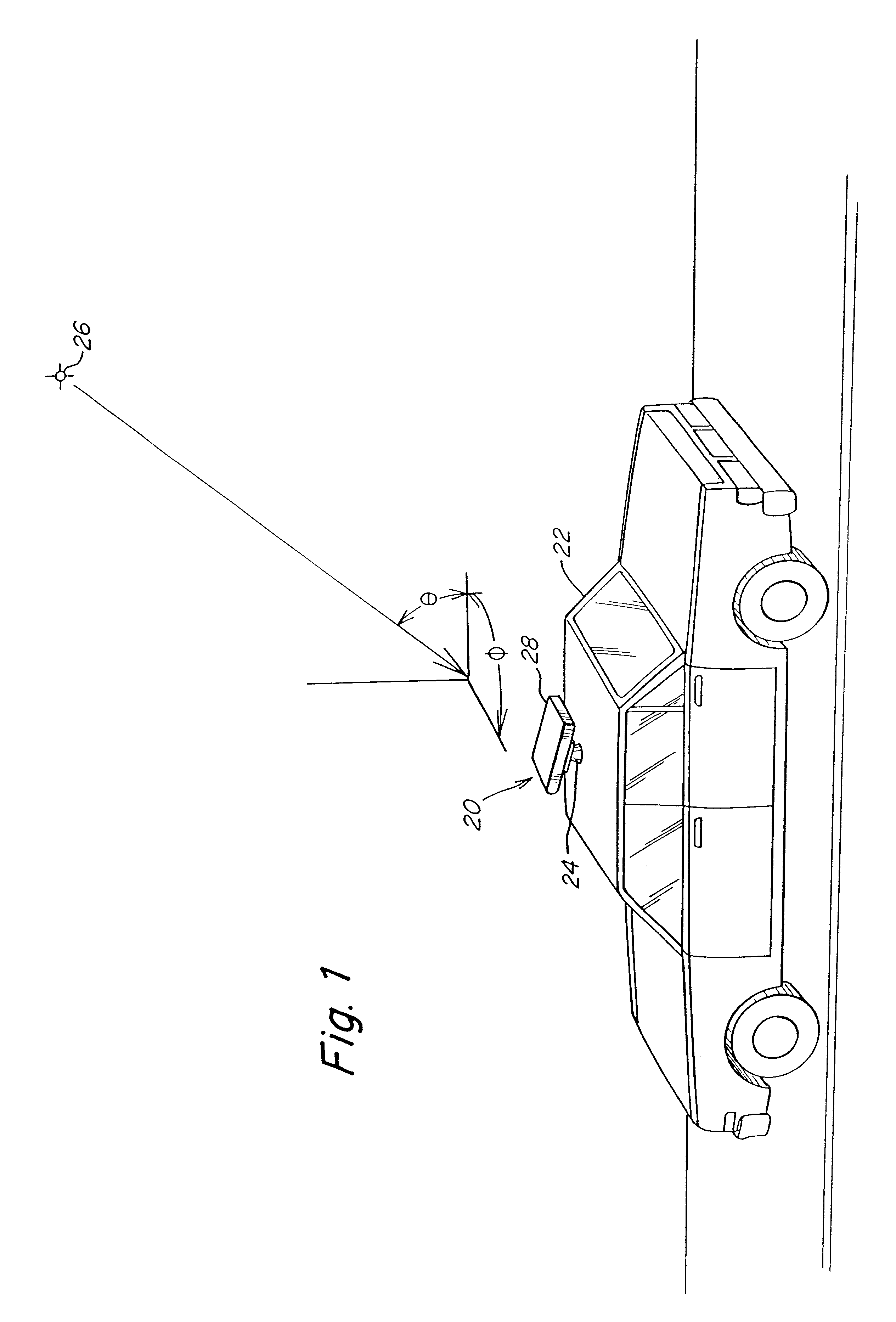
The antenna and system of the present invention provide, for example, any of live broadcast television programming, two-way communications signals, interactive service signals such as internet service, and other forms of data signals directly to passengers on mobile platforms such as, for example, airplanes, boats and automobiles. In a preferred embodiment, the antenna and system is to be used with existing digital satellite broadcasting satellites and technology to provide live broadcast television programming to the passengers. For example, in the preferred embodiment of the antenna and system of the invention, passengers in a vehicle can select and view live news channels, weather information, sporting events, network programming, and movies similar to programming that is available in most homes either through cable or satellite services. One advantage of the preferred embodiment of the antenna and system of the present invention is that the programming is live with no need for v...


PUM


Abstract

A leaky waveguide antenna array that receives and / or transmits electromagnetic signals includes a plurality of radiation waveguides disposed in parallel to each other on a surface plane to form the antenna array. A feed waveguide is located below the surface plane and provides an electromagnetic signal to the plurality of radiation waveguides and / or receives a plurality of electromagnetic signals from the plurality of radiation waveguides and provides a composite electromagnetic signal at an output of the feed waveguide. Each of the plurality of radiation waveguides has a waveguide axis and includes a plurality of apertures arranged in a direction of the waveguide axis. The feed waveguide includes a first section of waveguide having a first end connected to an input / output port. The first section of waveguide has a height substantially the same as the height of each of the plurality of radiation waveguides and the first section of waveguide has a second end coupled to a first junction point. The first junction point transitions from the first section of waveguide to a second section of waveguide and a third section of waveguide that each have a height that is substantially half of the height of the first section of waveguide. The second section of waveguide transitions with an upward sloping ramp to the substantially half height of the first section of waveguide. The third section of waveguide transitions with a downward sloping ramp to the substantially half height of the first section of waveguide.

Description

FIELD OF THE INVENTIONThe present invention relates to a video entertainment system for passenger vehicles and, more particularly, to a low-height, low-cost, high-gain, leaky wave antenna system disposed in a low-drag radome and a system for providing satellite broadcasted video directly to passengers on mobile platforms such as, for example, airplanes, boats and automobiles.BACKGROUND OF THE INVENTIONVarious embodiments of antennas for reception of satellite broadcasted signals designed for mounting on vehicles have been studied and proposed. Since such an antenna is to be mounted, for example, on a roof or the like of an automotive vehicle running on a road where the height of the cars are legally restricted or, for example, on an aircraft where height is also an issue with respect to, for example, any drag associated with such an antenna that may result in decreased fuel efficiency, an important feature of such an antenna is to minimize a height of the antenna and an antenna moun...

Claims


Application Information

Patent Timeline
Patent Type & Authority Patents(United States)
IPC IPC(8): H01Q21/06H01Q1/32H01P5/12H01Q13/20H01Q13/22H01Q21/00H04W88/02
CPCH01Q1/3275H01Q13/20H01Q13/22H01Q21/0006H01Q21/005H01Q21/068H01Q21/08
Inventor BARRETT, MICHAEL J.
Owner ASTRONICS AEROSAT CORP
Why Eureka
Try Eureka