Variable gain RF amplifier

Inactive Publication Date: 2009-10-22
STMICROELECTRONICS SRL
View PDF6 Cites 8 Cited by
  • Summary
  • Abstract
  • Description
  • Claims
  • Application Information

AI Technical Summary

Benefits of technology

[0018]According to a further aspect of the present invention, there is provided a system comprising receiving circuitry for receiving an RF signal; an input node coupled to the receiving circuitry; a variable current source comprising a control input coupled to the input node; first and second branches coupled in parallel between a first supply terminal and the variable current source, the first and second bran

Problems solved by technology

A drawback with such RF input circuitry is that in providing a low noise amplifier coupled to a variable gain amplifier, the current consumption is relatively high, and a relatively large amount of area is needed.
Furthermore, due to the number of components that are present through which the differential signal must pass, noise may be added to the system.

Method used


Image

  • Variable gain RF amplifier
  • Variable gain RF amplifier
  • Variable gain RF amplifier

Examples


Embodiment Construction

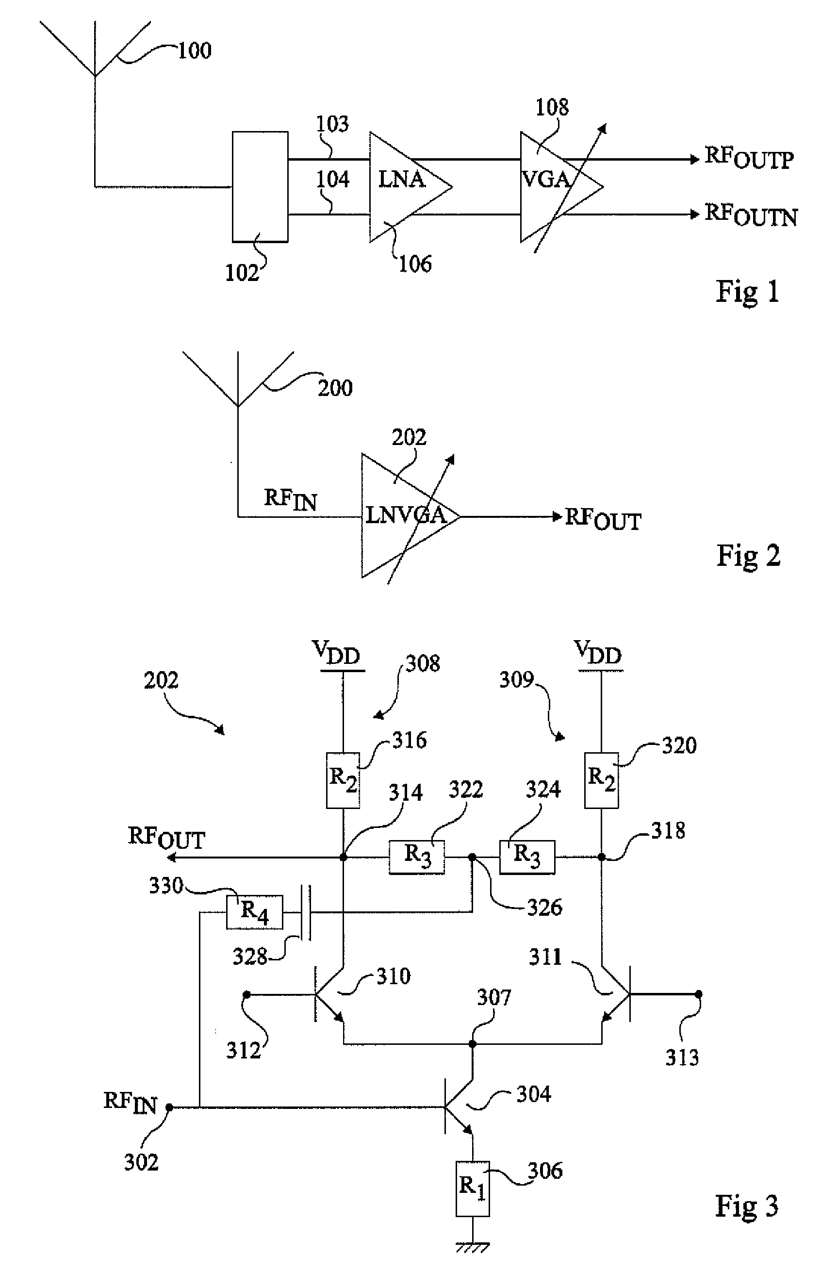
[0025]FIG. 1 illustrates input circuitry of an RF device for receiving an RF signal via an antenna 100. Antenna 100 is coupled to a balun 102, which converts an unbalanced signal into a balanced signal, and in particular the signal from the antenna into a differential signal comprising complementary parts. The differential signal is provided on two lines 103 and 104 to a low noise amplifier (LNA) 106, which amplifies the differential signal. The differential output of LNA 106 is coupled to a variable gain amplifier (VGA) 108, which amplifies the differential signal by a required amount such that the components of the differential output signal RFOUTP and RFOUTN have the required amplitudes. VGA 108 is controlled by a feedback loop.

[0026]Such an arrangement comprising separate circuitry for providing an LNA and a VGA has drawbacks, as discussed in the background section above. In particular, the LNA is likely to comprise at least one transistor for amplifying each part of the differe...


PUM


Abstract

A variable gain amplifier having an input node, a variable current source including a control input coupled to the input node, first and second branches coupled in parallel between a first supply terminal and the variable current source, the first and second branches defining a differential pair arranged to be controlled by first and second differential gain signals and having first and second output terminals, one of the output terminals including an output node of the variable gain amplifier; and a potential divider having a middle node coupled to the first and second output terminals, wherein the middle node is also coupled to the input node by a capacitor.

Description

CROSS-REFERENCE TO RELATED APPLICATIONS[0001]This application claims the priority benefit of European patent application number 083095110.2, filed on Apr. 18, 2008, entitled “VARIABLE GAIN RF AMPLIFIER,” which is hereby incorporated by reference to the maximum extent allowable by law.BACKGROUND OF THE INVENTION[0002]1. Field of the Invention[0003]The present invention relates to a variable gain RF amplifier, and in particular to a low noise variable gain RF amplifier.[0004]2. Discussion of the Related Art[0005]RF (radio frequency) devices such as radio tuners, mobile telephones, satellite receivers, TV tuners etc. are devices that receive an RF signal. In such devices, input circuitry comprising a low noise amplifier (LNA) is generally provided for amplifying the received RF signal which is for example received via an antenna. The LNA should introduce as little noise as possible to the signal. To avoid unwanted reflections, the input impedance of the LNA is usually matched to the im...

Claims


Application Information

Patent Timeline
IPC IPC(8): H03F3/45
CPCH03F3/19H03F3/45089H03G1/0023H03F2203/45392H03F2200/294
Inventor TOUZARD, OLIVIERTOURNIER, VERONIQUE
Owner STMICROELECTRONICS SRL
Why Eureka
Try Eureka