Component for a hearing aid and a method of making a component for a hearing aid

a technology for hearing aids and components, applied in the field of components for hearing aids, can solve the problems of undesired biofilms or otherwise irregular surface patinas, unsightly appearance, etc., and achieve the effect of superior properties in repellency

Active Publication Date: 2009-10-22
WIDEX AS
View PDF12 Cites 56 Cited by
  • Summary
  • Abstract
  • Description
  • Claims
  • Application Information

AI Technical Summary

Benefits of technology

[0017]This provides a component for a hearing aid that has enhanced repellency to moisture and bodily fluids. Components on which this surface would be advantageous comprise housings, casings, shells, faceplates, grids, hooks, lids, battery drawers, buttons and manipulators etc. Suitable substances for the coatings are silanes such as perfluoroalkylsilanes or alkylsilanes. The silanes are chemically attached to the surface by reaction between hydroxy groups on the silane and on the surface, forming a self assembled monolayer (SAM).
[0018]According to an embodiment, the component comprises a slab with an exterior surface that has been microstructured. The inventors have discovered that microstructuring of the surface enhances the water repellant properties. The term exterior surface is here used to designate a surface intended for generally facing the environment exterior to the hearing aid, as opposed to a surface intended to face inner parts of the hearing aid.

Problems solved by technology

Some of those factors may have a corroding influence; others may cause development of an undesired biofilm or of an otherwise irregular surface patina.
However the environmental factors may over time create an unsightly appearance.

Method used


Image

  • Component for a hearing aid and a method of making a component for a hearing aid
  • Component for a hearing aid and a method of making a component for a hearing aid
  • Component for a hearing aid and a method of making a component for a hearing aid

Examples


first embodiment

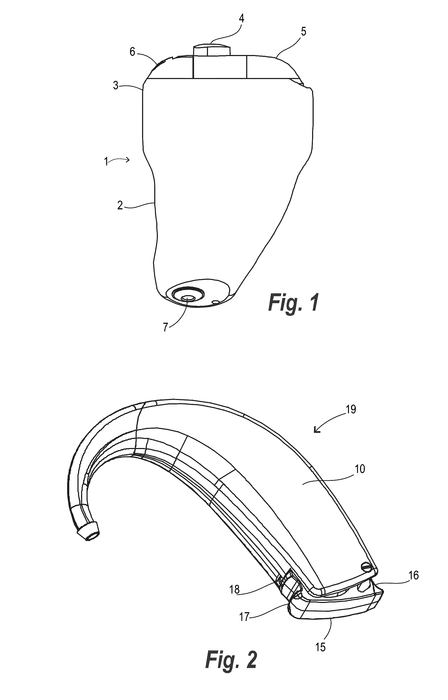
[0035]FIG. 2 shows a BTE hearing aid 19 this embodiment being essentially styled with hook and casing in one integral piece. This embodiment also has battery drawer 15 with battery drawer protrusion 16, and battery drawer nose 17. The FIG. 2 embodiment features a lock gripping portion 18, which is a manipulator that must be engaged by the tip of a nail or a pencil to permit opening the drawer for removal of the battery. For further details about these details reference may be had to WO-A1-2004073351, the contents of which are incorporated hereinto by reference.

second embodiment

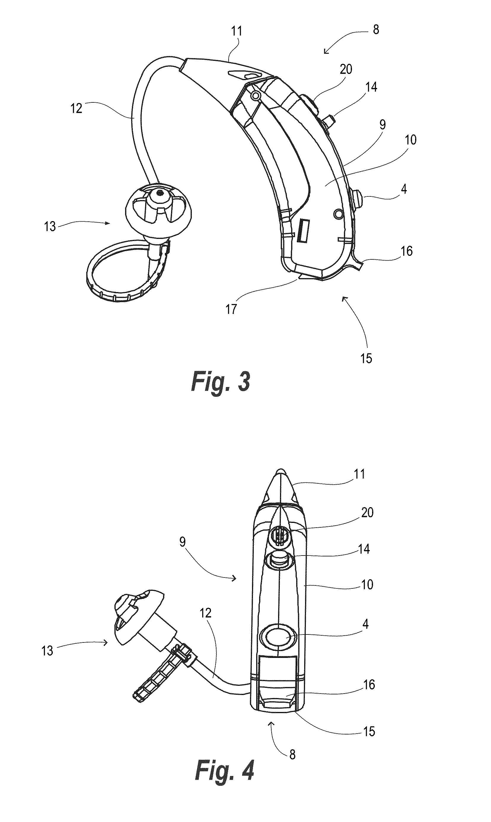
[0036]Reference is now made to FIG. 3 and FIG. 4 for an explanation of a BTE hearing aid according to the invention.

[0037]FIG. 3 illustrates a BTE hearing aid 8 according to the second embodiment, in side view. This hearing aid 8 comprises BTE housing 9, generally consisting of casing 10, hook 11, sound tube 12 and ear piece 13. The hearing aid has various details such as microphone grid 20, rocker button 14, battery drawer 15, battery drawer protrusion 16, and battery drawer nose 17. The rocker button is used for permitting the user to turn up or down the volume. The battery drawer may be partially opened by engaging the protrusion 16 for switching off the hearing aid, and closed to switch on the hearing aid again. The battery drawer may also be fully opened for removing the battery by engaging the nose 17. For a further explanation about these details reference may be had to WO-A1-2004073351.

[0038]FIG. 4 shows the BTE hearing aid of FIG. 3 in rear view. Reference may be had to th...


PUM

PropertyMeasurementUnit
heightaaaaaaaaaa
water contact angleaaaaaaaaaa
heightaaaaaaaaaa

Abstract

A hearing aid (8) comprises an inlet port (6), a sound tube (12) for conveying sound to the ear piece (13). The invention further provides a component for a hearing aid comprising a slab (26) having an exterior surface, which is super-hydrophobic. The component may be any one of a housing, a casing, a shell, a faceplate, a grid, a hook, a lid, a battery drawer, a button, or a manipulator. The invention also provides a method of manufacturing a component for a hearing aid.

Description

RELATED APPLICATIONS[0001]The present application is a continuation-in-part of application no. PCT / DK2007000002 filed on Jan. 3, 2007, and published as WO-A1-2008080397, the contents of which are incorporated herein by reference.BACKGROUND OF THE INVENTION[0002]1. Field of the Invention[0003]The present invention relates to components for hearing aids. The invention further relates to a method for manufacturing a component for a hearing aid.[0004]2. The Prior Art[0005]Hearing aids generally include a range of components such as housing, internal electronic circuitry, lid, switches and buttons.[0006]ITE hearings aids generally comprise a shell, which anatomically duplicates the relevant part of the user's ear canal. A receiver is placed in the shell in communication with an acoustic outlet port arranged at the proximal end, i.e. the end of the shell adapted for being situated in the ear canal close to the tympanic membrane. The distal end of the shell, i.e. the opposite end, intended...

Claims


Application Information

Patent Timeline
Patent Type & Authority Applications(United States)
IPC IPC(8): H04R25/00H04R31/00
CPCH04R25/65H04R25/658Y10T29/49002Y10T29/53174Y10T29/49005Y10T29/5313
Inventor VESTERGAARD, JORN EILEROLSEN, JORGEN MEJNERCHRISTENSEN, LEIF HOJSLETHAUGSHOJ, KENNETH BRIANJENSEN, MARTIN FROHLINGVESTENTOFT, KASPER
Owner WIDEX AS
Why Eureka
Try Eureka