Combustion Turbine Including a Diffuser Section with Cooling Fluid Passageways and Associated Methods

a combustion turbine and diffuser technology, applied in the direction of machines/engines, stators, liquid fuel engines, etc., can solve the problems of insufficient fluid delivery and inability to re-energize the boundary layer, and achieve the effect of enhancing the attachment of the boundary layer adjacent and enhancing the attachment of the boundary layer

Inactive Publication Date: 2009-10-22
SIEMENS ENERGY INC
View PDF13 Cites 53 Cited by
  • Summary
  • Abstract
  • Description
  • Claims
  • Application Information

AI Technical Summary

Benefits of technology

[0012]Another aspect is directed to a method of making a diffusion section for a combustion turbine so that surfaces of the diffusion section have enhanced attachment of a boundary layer adjacent thereto. The diffusion section may comprise an outer wall, an inner wall, and at least one strut member extending therebetween. The method may include forming at least one first gas p

Problems solved by technology

Since the fluid flow may slow as it travels from the diffuser inlet to the diffuser outlet, the fluid flow available to a vortex generator closer to the diffuser outlet may be unable to sufficiently re-energize the boundary layer to prevent separati

Method used


Image

  • Combustion Turbine Including a Diffuser Section with Cooling Fluid Passageways and Associated Methods
  • Combustion Turbine Including a Diffuser Section with Cooling Fluid Passageways and Associated Methods
  • Combustion Turbine Including a Diffuser Section with Cooling Fluid Passageways and Associated Methods

Examples


Embodiment Construction

[0017]The present invention will now be described more fully hereinafter with reference to the accompanying drawings, in which preferred embodiments of the invention are shown. This invention may, however, be embodied in many different forms and should not be construed as limited to the embodiments set forth herein. Rather, these embodiments are provided so that this disclosure will be thorough and complete, and will fully convey the scope of the invention to those skilled in the art. Like numbers refer to like elements throughout, and prime and multiple prime notation is used to indicate similar elements in alternative embodiments.

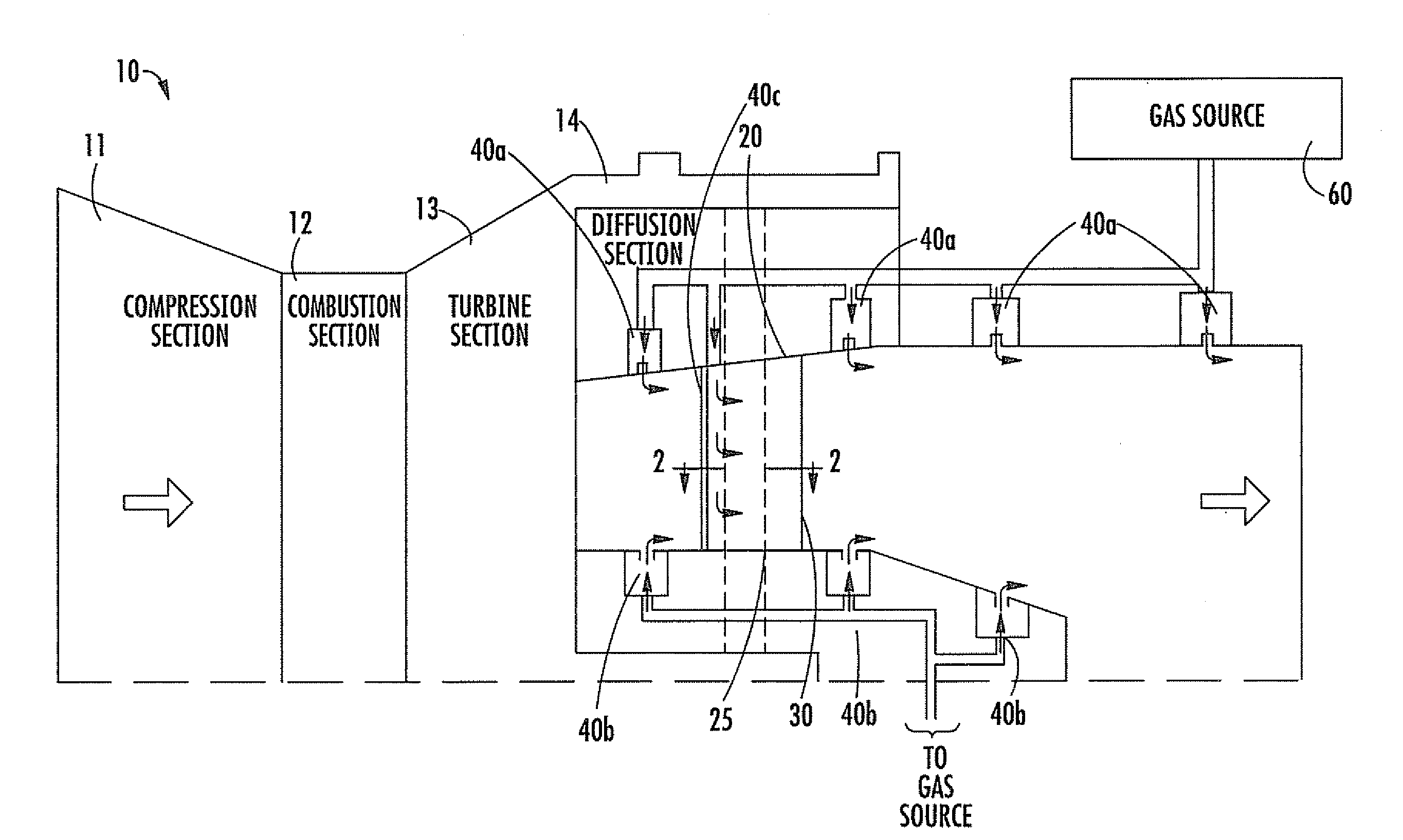
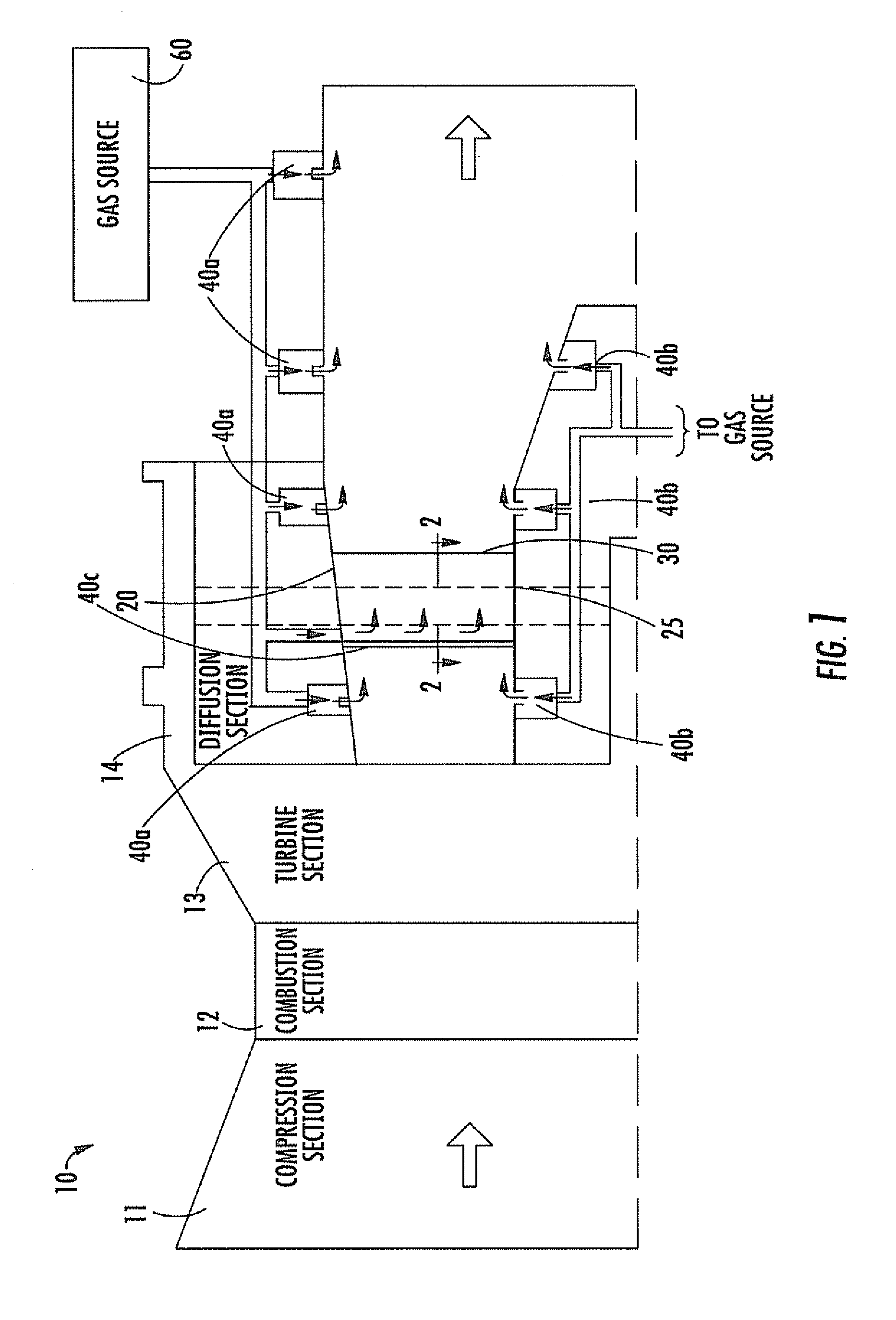
[0018]Referring initially to FIGS. 1 and 2, a first embodiment of a combustion turbine 10 is now described. The combustion turbine 10 illustratively comprises a compressor section 11, a combustion section 12 downstream from the compressor section, and a turbine section 13 downstream from the combustion section. A diffuser section 14 is downstream from the...


PUM


Abstract

A combustion turbine includes a compressor section, a combustion section downstream from the compressor section, and a turbine section downstream from the combustion section. A diffuser section is downstream from the turbine section and has an outer wall, an inner wall, and at least one strut member extending therebetween. The outer wall has at least one first gas passageway therein, the inner wall has at least one second gas passageway therein, and the at least one strut member has at least one third gas passageway therein. The at least one first, second and third gas passageways deliver gas therethrough to assist attachment of a boundary layer to adjacent surfaces of the outer wall, the inner wall, and the at least one strut, respectively.

Description

FIELD OF THE INVENTION[0001]The present invention relates to the field of combustion turbines, and, more particularly, to a combustion turbine including a diffuser section and associated methods.BACKGROUND OF THE INVENTION[0002]A combustion turbine typically includes, in a serial flow relationship, a compressor section to compress the entering airflow, a combustion section in which a mixture of fuel and the compressed air is burned to generate a propulsive gas flow, and a turbine section that is rotated by the propulsive gas flow. After passing through the turbine section, the propulsive gas flow exits the engine through a diffuser section. In ground based combustion turbines used for electricity generation, power is normally extracted from the rotating shaft to drive an electrical power generator.[0003]The efficiency of a combustion turbine is related to the combustion temperature. In the pursuit of greater combustion turbine efficiency, components formed from new materials are des...

Claims


Application Information

Patent Timeline
IPC IPC(8): F01D25/14
CPCF01D25/14
Inventor LITTLE, DAVID A.PAPROTNA, HUBERTUS E.LIGHT, KEVIN M.
Owner SIEMENS ENERGY INC
Why Eureka
Try Eureka