Mold Base for Mold Manufacturing Thermoplastic Containers, and Molding Device Equipped With At Least One Mold Provided With Such a Base

a mold manufacturing and thermoplastic container technology, applied in the field of mold manufacturing thermoplastic containers, can solve the problems of container not being able to stand on a support in a stable manner, most difficult to manufacture, container shape loss, etc., and achieve the effect of reducing the width of the bottom, reducing the width of the cavity base, and facilitating removal

Inactive Publication Date: 2009-10-22
SIDEL PARTICIPATIONS SAS
View PDF9 Cites 11 Cited by
  • Summary
  • Abstract
  • Description
  • Claims
  • Application Information

AI Technical Summary

Benefits of technology

[0018]The fact to adopt, according to the invention, a cavity bottom width l as small as 1.5 to 3.5 mm surely runs counter to the solution conventionally adopted which is to have a more substantial cavity base width, typically of at least 6 mm: wide cavities make it easier to remove the air trapped between the wall of the mold and the wall of the foot of the container during blowing, allowing the thermoplastic wall that is in the process of being deformed to actually reach the wall of the mold and therefore making it possible to obtain a container with correctly formed feet.
[0019]Surely, as such, cavities of narrow width as recommended in the context of the present invention make the feet more difficult to blow-mold into their correct shape. However, with the reduction in the width of the bottoms of cavities the invention combines a reduced dorsal fin height of between about 16.5 and 18 mm, as opposed to a height in excess of 18 mm in a conventional mold: the deforming of the thermoplastic which on the one hand is made more difficult in the bottoms of the cavities because of the narrower width of said bottoms is, by contrast, made easier in the region of the dorsal fins because of the shorter height of the dorsal fins. In addition, the concave shape of the dorsal fin flanks and the very wide angle of 52° to 88°, as opposed to an angle of the order to 49° in current designs, of the dorsal fin flanks also make a positive contribution.
[0020]Finally, the overall end-result provided by a mold base designed according to the invention is due to a container base that is molded more accurately and is better able to withstand pressure and heat.

Problems solved by technology

The part of the containers that is the most difficult to manufacture is the base.
It is effectively the base which supports the weight of the column of liquid contained in the container and, if it has insufficient mechanical strength, it loses its shape and the container can no longer stand in a stable manner on a support.
This means that, in relative terms, it requires more material than the body of the container the wall of which has currently been reduced down to a very small thickness that is becoming difficult to reduce further.
What is more, the base is the region of the container that is the most difficult to shape correctly in the blow-molding or stretch-blow-molding operation, specifically because the appreciably greater thickness of material makes it slower to stretch and less easy to shape.

Method used


Image

  • Mold Base for Mold Manufacturing Thermoplastic Containers, and Molding Device Equipped With At Least One Mold Provided With Such a Base
  • Mold Base for Mold Manufacturing Thermoplastic Containers, and Molding Device Equipped With At Least One Mold Provided With Such a Base
  • Mold Base for Mold Manufacturing Thermoplastic Containers, and Molding Device Equipped With At Least One Mold Provided With Such a Base

Examples


Embodiment Construction

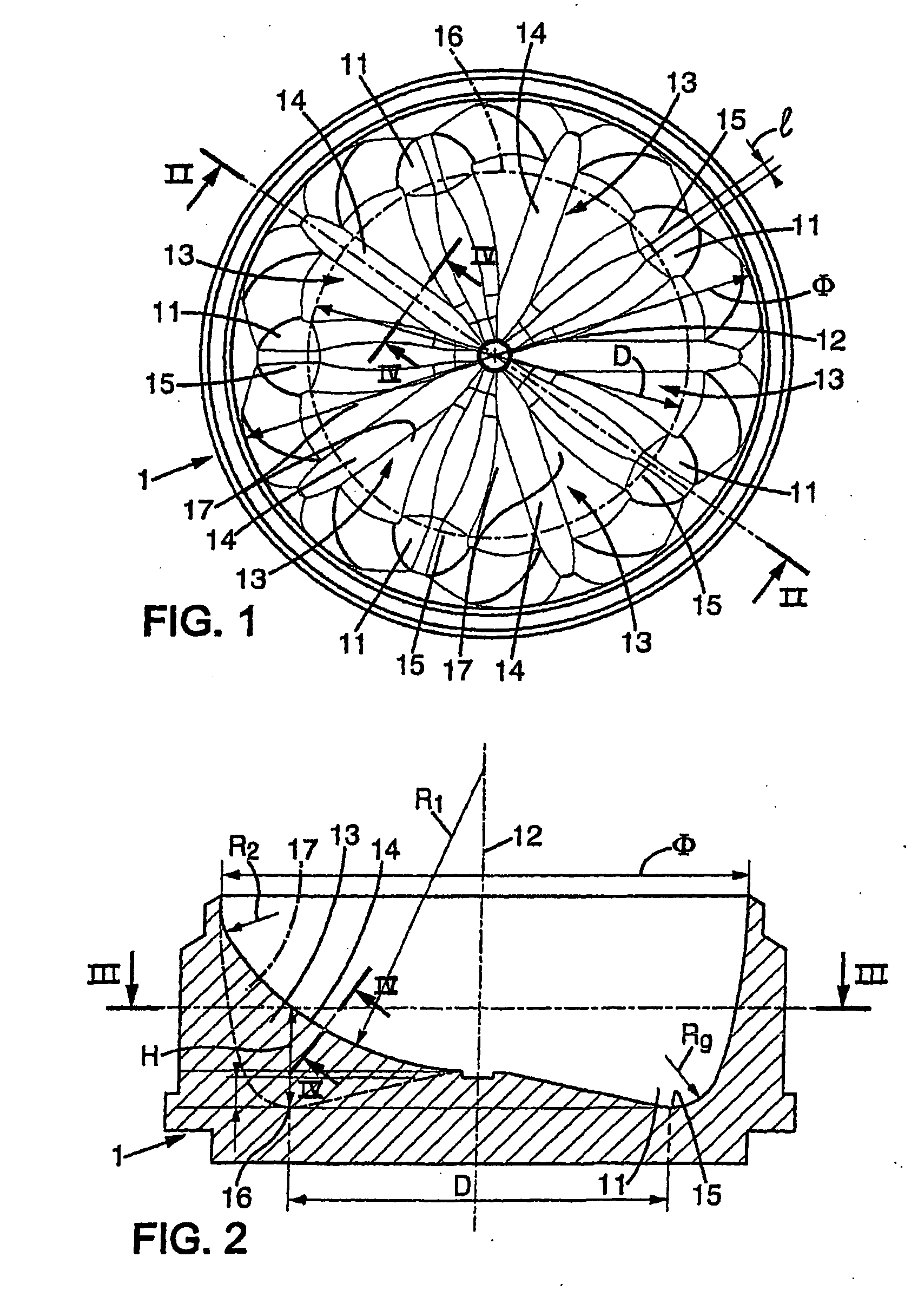
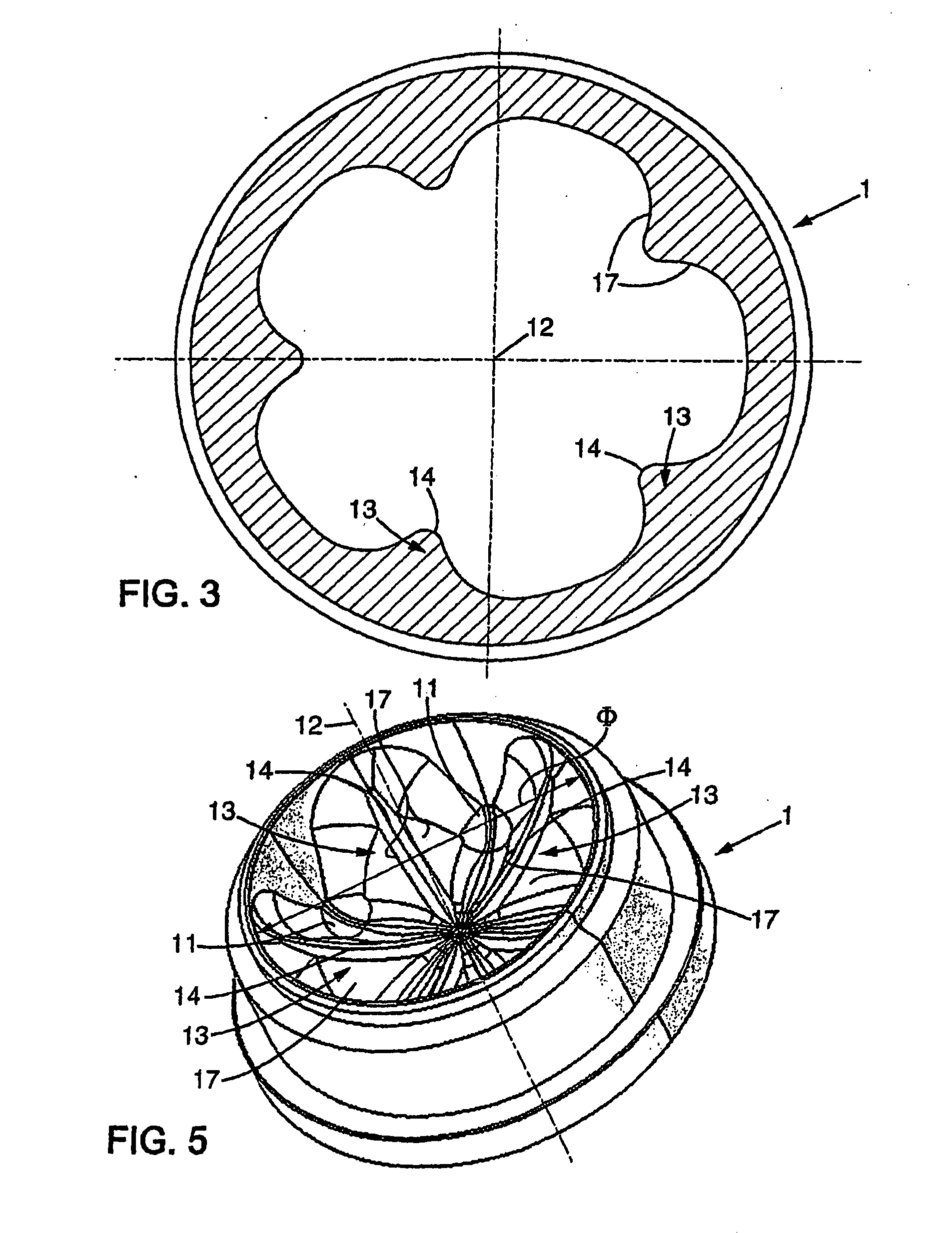
[0037]Reference is now made to FIGS. 1 to 5 which depict a mold base 1 intended to be fitted to a mold for the manufacture, by blow-molding or stretch-blow-molding, of containers, particularly bottles, made of a thermoplastic such as PET.

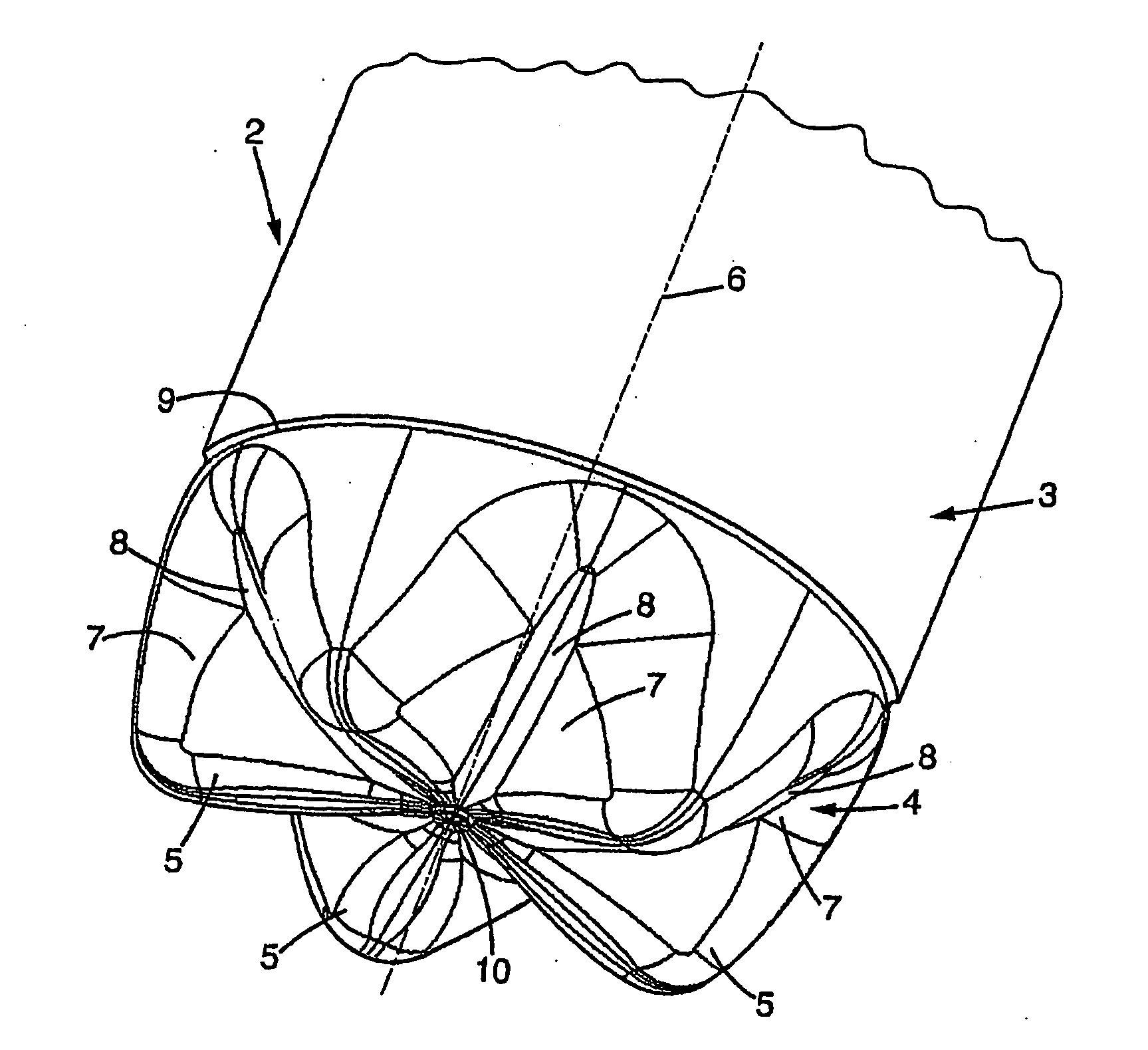
[0038]As shown in FIG. 6, the containers 2 that are to be manufactured with this mold have a body 3 and have a base 4 of the type known as petalloid having five foot-forming protrusions 5 which are distributed angularly at equal distances apart, which run approximately parallel to the axis 6 of the container and are separated from one another by radiating valleys 7 the bottoms 8 of which run in a convex radial curve. All the valleys 7 converge at the center of the base, which is made in the form of a plateau 10 projecting outwards slightly. The container base 4 is connected to the container body 3 by a connecting region 9 that is substantially a cylinder of revolution having a diameter Φ of about 85 to 95 mm.

[0039]With reference now to FIGS. 1 to 5,...


PUM

PropertyMeasurementUnit
diameteraaaaaaaaaa
diameteraaaaaaaaaa
diameteraaaaaaaaaa

Abstract

The invention concerns a mold base (1) for a blow- or stretch-blow molding of thermoplastic containers having a petaloid base with 5 stems which are separated by radiating troughs with convex radially curvilinear base, said base being connected to a body with a diameter Φ of 85 to 95 mm; the base comprises 5 cavities (11) separated by radiating ridge lines (13) with concave radial ridge (4) having a radius of 2 to 5 mm; the bases (15) of the cavities (11) have each a width of 1.5 to 3.5 mm and are distributed over a circular contour (16) of diameter of base D of 60 to 66 mm; the height (H) of the ridge line is 16.5 to 18 mm; the flanks (17) of the ridge lines are axially concave and the tangent planes at origin form an angle of 52° to 88°.

Description

FIELD OF THE INVENTION[0001]The present invention relates in general to the field of the manufacture, by blow-molding or stretch-blow-molding, of containers, particularly bottles, made of thermoplastic such as PET.[0002]More specifically, the invention relates to improvements made to the design of a mold base for a mold for the manufacture, by blow-molding or stretch-blow-molding, of containers, particularly of bottles, made of thermoplastic such as PET, said containers having a body and having a base of the type said petalloid with five feet which are distributed angularly with uniform spacing, which run approximately parallel to the axis of the container and which are separated from one another by radiating valleys the bottoms of which run radially with a convex curvature, which container base connects with the container body in a connection region that is substantially of a cylinder of revolution having a diameter Φ of about 85 to 95 mm, said mold base comprising, for molding sai...

Claims


Application Information

Patent Timeline
Patent Type & Authority Applications(United States)
IPC IPC(8): B29C49/48
CPCB29C49/12B29C49/48B65D1/0261B29K2067/00B29L2031/7158B29C2049/4892
Inventor LESUEUR, FRANCOIS
Owner SIDEL PARTICIPATIONS SAS
Why Eureka
Try Eureka