Eureka AIR delivers breakthrough ideas for toughest innovation challenges, trusted by R&D personnel around the world.

Self-sharpening tool blade and method

Inactive Publication Date: 2009-10-22
LESCHE PETER W
View PDF5 Cites 10 Cited by
  • Summary
  • Abstract
  • Description
  • Claims
  • Application Information

AI Technical Summary

Benefits of technology

[0005]It is an object of the present invention to provide a tool blade which uses the forces that normally dull the forward cutting edge of the blade to make it self-sharpening.
[0011]These and other objectives are accomplished by the present invention, a self-sharpening tool blade to be used on shovels, spades, cultivating tools, garden hand tools, and other tools and mechanical equipment which need to have consistently sharp cutting edges in order to penetrate into and dig in the ground. The blade utilizes the concept of differential surface wear for self-sharpening. The back side of the tool blade sustains more wear than the top side, since it is most often in contact with more abrasive soil and earth debris, while the blade's top side is usually in contact with abrasive materials which exert less abrasion and less pressure than that which the back side experiences. This is due to the manner in which digging occurs; that is the top side of the blade contacts soil and soil debris which is free to move away from the blade during digging, whereas soil material contacting the back side of the blade is, for the most part, compacted and immovable, providing a higher degree of abrasive friction. The difference in abrasive forces and pressure differential between the top side and back side of the blades serves to maintain and, over time, sharpens the taper angle of the blade.

Problems solved by technology

It has been found that under normal usage of these types of bladed tools, the front or leading edge of the blade becomes dull due to the method of sharpening applied at the time of original manufacture.
In use, the normal abrasion of the cutting edge of these types of blades occurs primarily on the back sides of the blades, causing the leading edges of the blades to wear down.
This causes the top side cutting edge of the blade to wear more quickly and become dull and, of course, tools with dull blades are ineffective.
However, none of these prior attempts have been successful in providing a simple, highly effective and simply designed self-sharpening blade product.

Method used


Image

  • Self-sharpening tool blade and method
  • Self-sharpening tool blade and method
  • Self-sharpening tool blade and method

Examples


Embodiment Construction

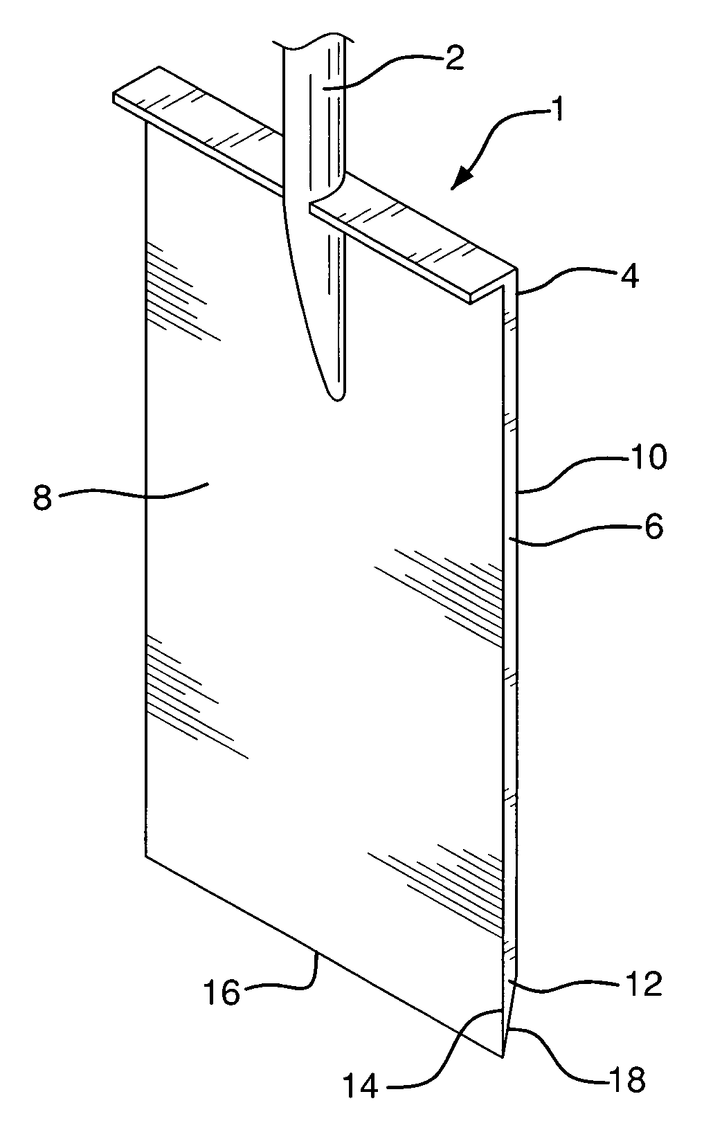
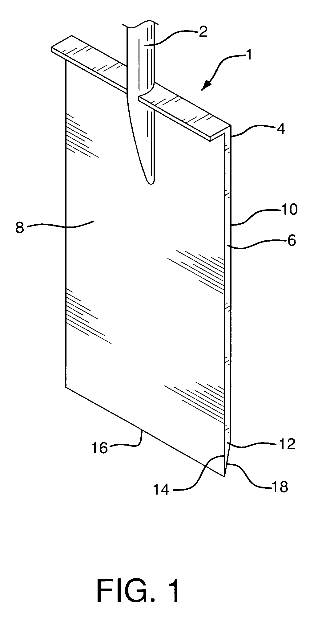
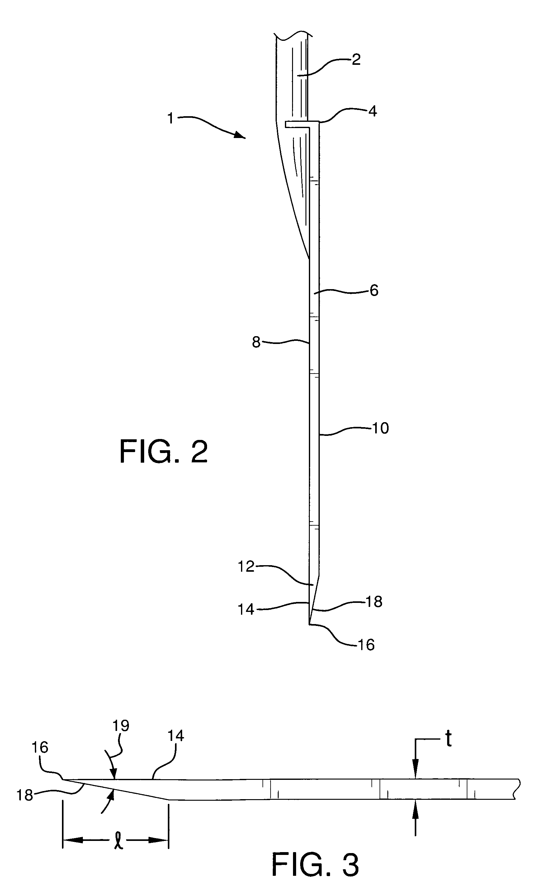
[0018]Tool 1 comprises handle 2 and blade 4, configured to penetrate into the surface of the ground and dig within the ground. Blade 4 comprises rear section 6 having top side 8 and back side 10, and tapered front edge section 12 having top surface 14 contiguous with top side 8 of rear section 6. Top surface 14 is shown as being in the same transverse plane as top side 8. It is within the scope of the invention and is contemplated that top surface 14 could be configured at an angle to top side 8.

[0019]Front edge section 12 also comprises forwardmost edge tip 16 and bottom surface 18 tapered at an acute taper angle 19 from tip 16 and extending to back side 10 of rear section 6 of blade 4. Tip 16 is a sharp edge surface configured for penetration of the ground, cutting into roots, etc.

[0020]In use, front edge section 12 of blade 4 is compelled into and penetrates surface 20 of ground 22 to remove material, in most cases soil. As this is done, blade 4 itself is driven and then inserted...


PUM

PropertyMeasurementUnit
Lengthaaaaaaaaaa
Thicknessaaaaaaaaaa
Forceaaaaaaaaaa

Abstract

A self-sharpening tool blade is to be used on shovels, spades, cultivating tools, garden hand tools, and other tools and mechanical equipment which need to have consistently sharp cutting edges in order to penetrate into and dig in the ground. The blade utilizes the concept of differential surface wear for self-sharpening. The back side of the tool blade sustains more wear than the top side, since it is most often in contact with more abrasive soil and earth debris, while the blade's top side is usually in contact with abrasive materials which exert less abrasion and less pressure than that which the back side experiences. This is due to the manner in which digging occurs; that is the top side of the blade contacts soil and soil debris which is free to move away from the blade during digging, whereas soil material contacting the back side of the blade is, for the most part, compacted and immovable, providing a higher degree of abrasive friction. The difference in abrasive forces and pressure differential between the top side and back side of the blades serves to maintain and, over time, sharpens the taper angle of the blade.

Description

BACKGROUND OF THE INVENTION[0001]The invention relates to the field of metal blades used to penetrate the earth for digging, moving soil and root cutting; especially those blades used for heavy manual and / or mechanical work performed by gardeners, landscapers, nurserymen, hardscapers, contractors, road builders, farmers and like workers. It has been found that under normal usage of these types of bladed tools, the front or leading edge of the blade becomes dull due to the method of sharpening applied at the time of original manufacture. These blades are normally sharpened on what would be considered the top side of the blade, as exemplified in U.S. Pat. No. 4,396,214.[0002]In use, the normal abrasion of the cutting edge of these types of blades occurs primarily on the back sides of the blades, causing the leading edges of the blades to wear down. This results from the fact that, during the digging operation, the soil, dirt, debris, etc. on the back side of the blade is normally hard...

Claims


Application Information

Patent Timeline
IPC IPC(8): B24B1/00B26B9/02
CPCB24D15/06A01B1/02
Inventor LESCHE, PETER W.
Owner LESCHE PETER W
Why Eureka
Eureka Blog
Learn More