Gear Drive Damper

a technology of gear drive and damper, which is applied in the direction of lighting and heating apparatus, ventilation systems, heating types, etc., can solve the problems of complicated mechanical linkages and difficult servi

Active Publication Date: 2009-10-22
AIR SYST
View PDF18 Cites 79 Cited by
  • Summary
  • Abstract
  • Description
  • Claims
  • Application Information

AI Technical Summary

Benefits of technology

[0007]According to one aspect of the invention, an air damper assembly is provided for regulating an air flow. The air damper assembly includes a frame that is adapted to be mounted in relationship to the air flow. The air damper assembly also includes a plurality of elongated damper blades rotatably mounted to the frame for rotational movement between an open position and a closed position. The air damper assembly further includes a drive mechanism for actuating the damper blades between the open and closed positions. The drive mechanism includes a gear that is fixedly secured to a distal end of each of the plurality of damper blades and an elongated rack that is slidably coupled to the frame. The rack meshingly engages the gears such that linear movement of the rack in a first linear direction results in rotational movement of the plurality of damper blades in a first rotational direction and linear movement of the rack in a second linear direction opposite the first linear direction results in rotational movement of the plurality of damper blades in a second rotational direction opposite the first rotational direction.
[0008]According to another aspect of the invention, an air damper assembly is provided for regulating an air flow. The air damper assembly includes a frame that is adapted to be mounted in relationsh...

Problems solved by technology

Such mechanical linkages are complicated, include multiple connections and joints which ...

Method used


Image

  • Gear Drive Damper
  • Gear Drive Damper
  • Gear Drive Damper

Examples


second embodiment

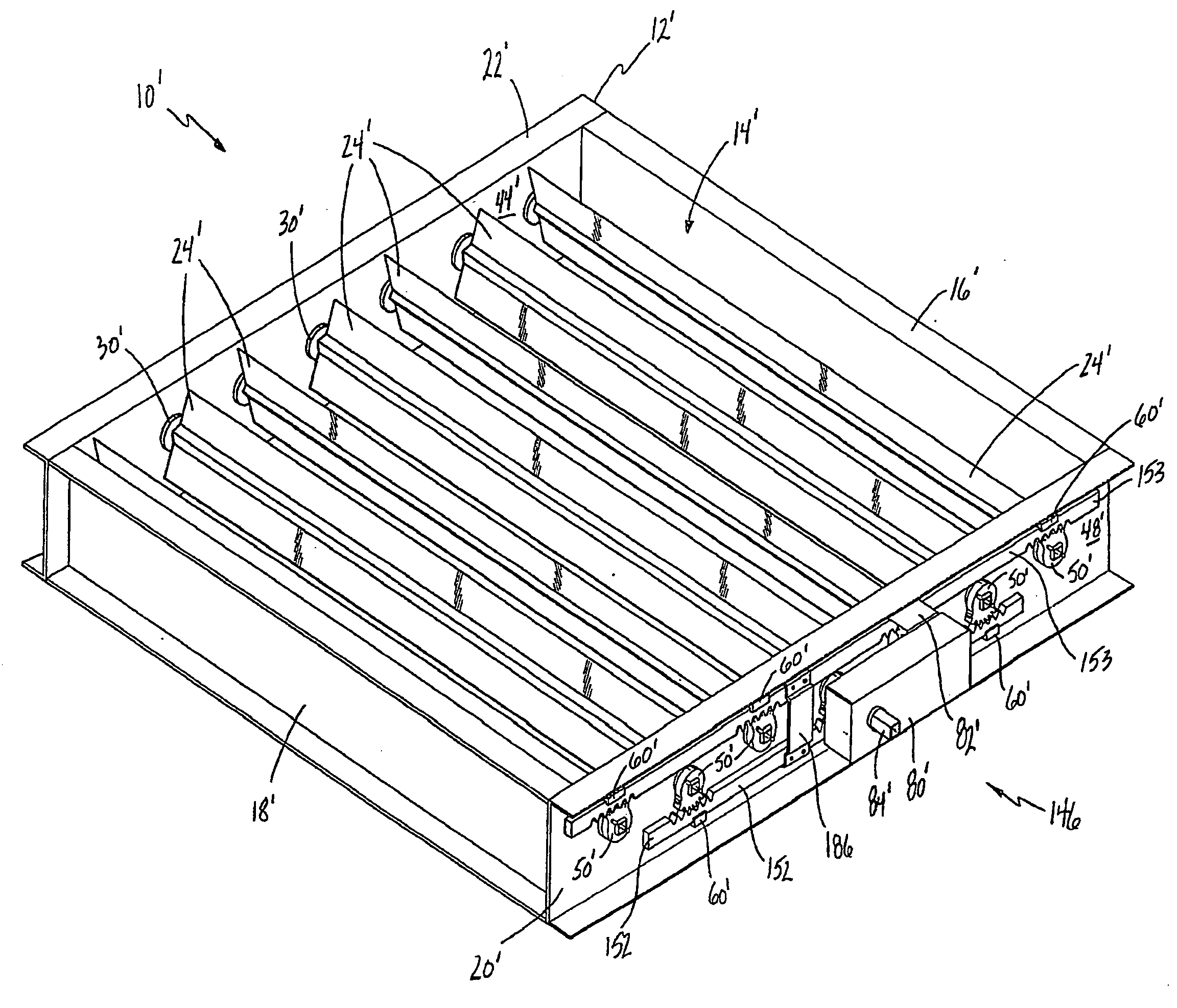
[0031]Referring to FIGS. 8 and 9, wherein like primed reference numerals represent similar elements as those described above, in the invention the air damper assembly 10′ includes a plurality of opposed damper blades 24′. More specifically, damper blades 24′ on adjacent shafts 26′ are oriented such that adjacent damper blades 24′ rotate in opposite directions between the open and closed positions.

[0032]As described above, the flow area of the air inlet opening 14′ is maximized when the damper blades 24′ are rotated to the open position, whereat the damper blades 24′ are substantially coplanar with the air flow. Contrarily, the flow area of the air inlet opening 14′ is minimized, or even sealed tight, when the damper blades 24′ are rotated to the closed position, whereat the damper blades 24′ are transverse to the air flow.

[0033]The damper blades 24′ are operatively coupled together and are rotated simultaneously between the open and closed positions by a drive mechanism, generally s...
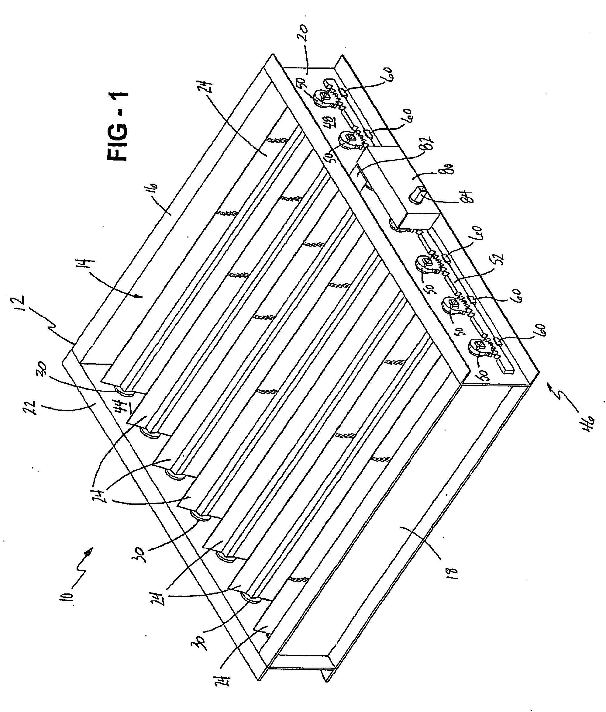
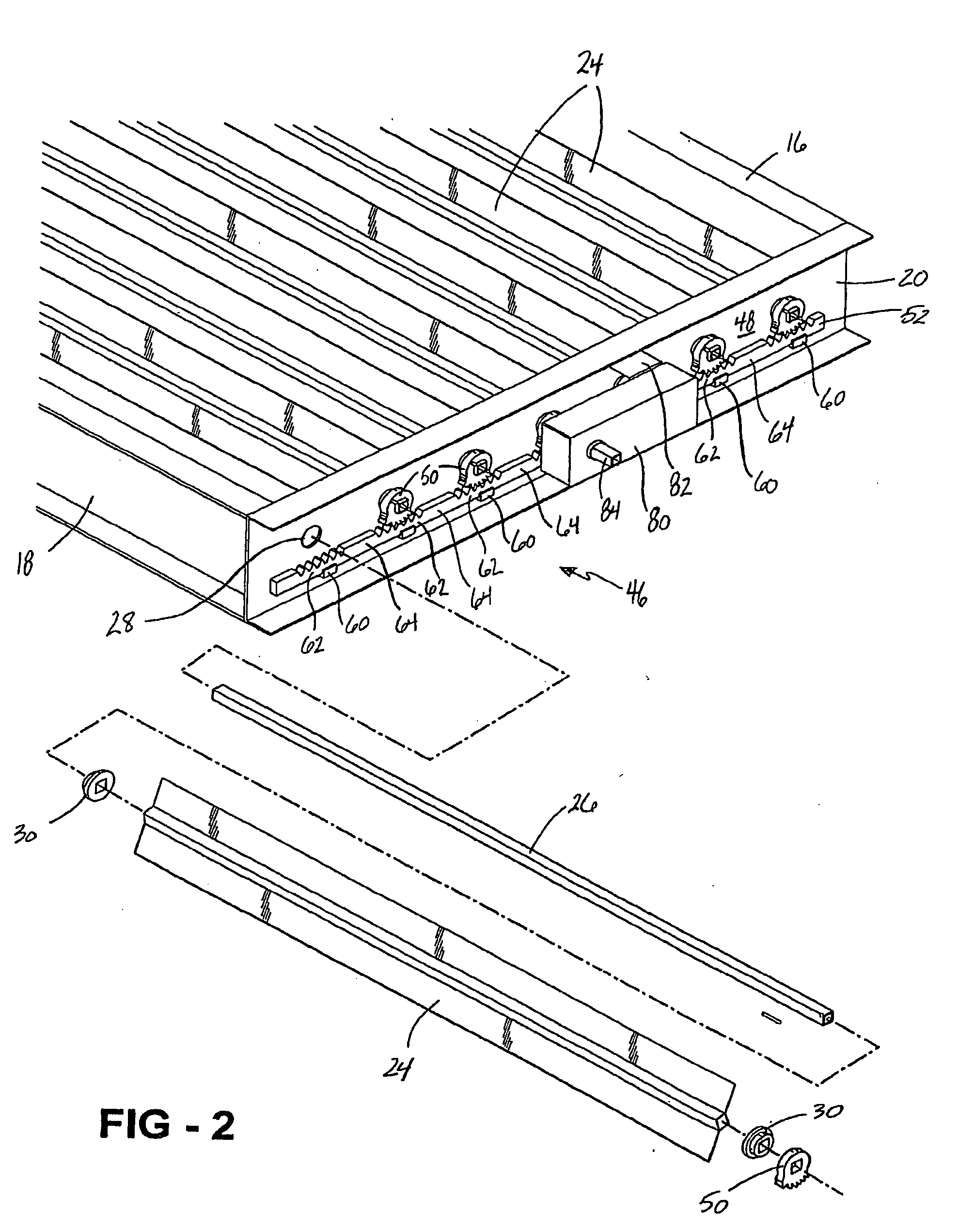
first embodiment

[0034]As described above with respect to the first embodiment, the first 152 and second 153 racks are slidably supported by a plurality of rack supports 60′ fixedly secured to the side member 20′ of the frame 12′. In the embodiment shown, the number of rack supports 60′ for the first rack 152 corresponds to the number of gears 50′ that meshingly engage the first rack 152 such that there is one rack support 60′ located directly below each one of the gears 50′. It is appreciated, however, that more or less rack supports 60′ can be used for supporting the first rack 152 without varying from the scope of the invention. Similarly, the number of rack supports 60′ for the second rack 153 corresponds to the number of gears 50′ that meshingly engage the second rack 153 such that there is one rack support 60′ located directly above each one of the gears 50′. It is appreciated, however, that more or less rack supports 60′ can be used for supporting the second rack 153 without varying from the ...


PUM

PropertyMeasurementUnit
Flexibilityaaaaaaaaaa
Molecular weightaaaaaaaaaa

Abstract

An air damper assembly for regulating an air flow includes a frame, a plurality of elongated damper blade rotatably mounted to the frame, and a drive mechanism for actuating the damper blades between open and closed positions. The drive mechanism includes a gear fixedly secured to a distal end of each of the damper blades and an elongated rack slidably coupled to the frame. The rack meshingly engages the gears such that linear movement of the rack in a first linear direction results in rotational movement of the damper blades in a first rotational direction and linear movement of the rack in a second linear direction opposite the first linear direction results in rotational movement of the damper blades in a second, rotational direction opposite the first rotational direction

Description

BACKGROUND OF THE INVENTION[0001]1. Field of the Invention[0002]The invention relates to air damper assemblies particularly for heating, ventilating and air conditioning systems. More particularly, the invention relates to air damper assemblies of the type that have a plurality of damper blades mounted for pivotal movement to regulate the volume of air that can be passed therethrough, or to completely block such air flow.[0003]2. Description of the Related Art[0004]Air damper assemblies including moveable louvers or damper blades for regulating air flow or completely blocking such air flow are well known in the art. Generally, an air damper assembly includes a rectangular frame for mounting of the air damper assembly in a suitable position with respect to the air flow. The frame includes a frame opening defining a flow area through which the air flow passes.[0005]A plurality of damper blades, all of which are typically identical, is disposed horizontally within the frame opening. Ea...

Claims


Application Information

Patent Timeline
IPC IPC(8): F24F13/14
CPCA61K31/352A61K31/05F24F13/1426F24F2013/1446
Inventor TINSLEY, BARTONSHEPARD, CHARLES
Owner AIR SYST
Why Eureka
Try Eureka