
Optimizing neighbor lists

a neighbor list and neighbor list technology, applied in the direction of electrical equipment, wireless communication, etc., can solve the problems of not being able to scan all possible channels or id codes, not being able to achieve the effect of superior performance, and requiring manual optimization

Inactive Publication Date: 2009-10-22
APPLE INC
View PDF2 Cites 29 Cited by
  • Summary
  • Abstract
  • Description
  • Claims
  • Application Information

AI Technical Summary

Benefits of technology

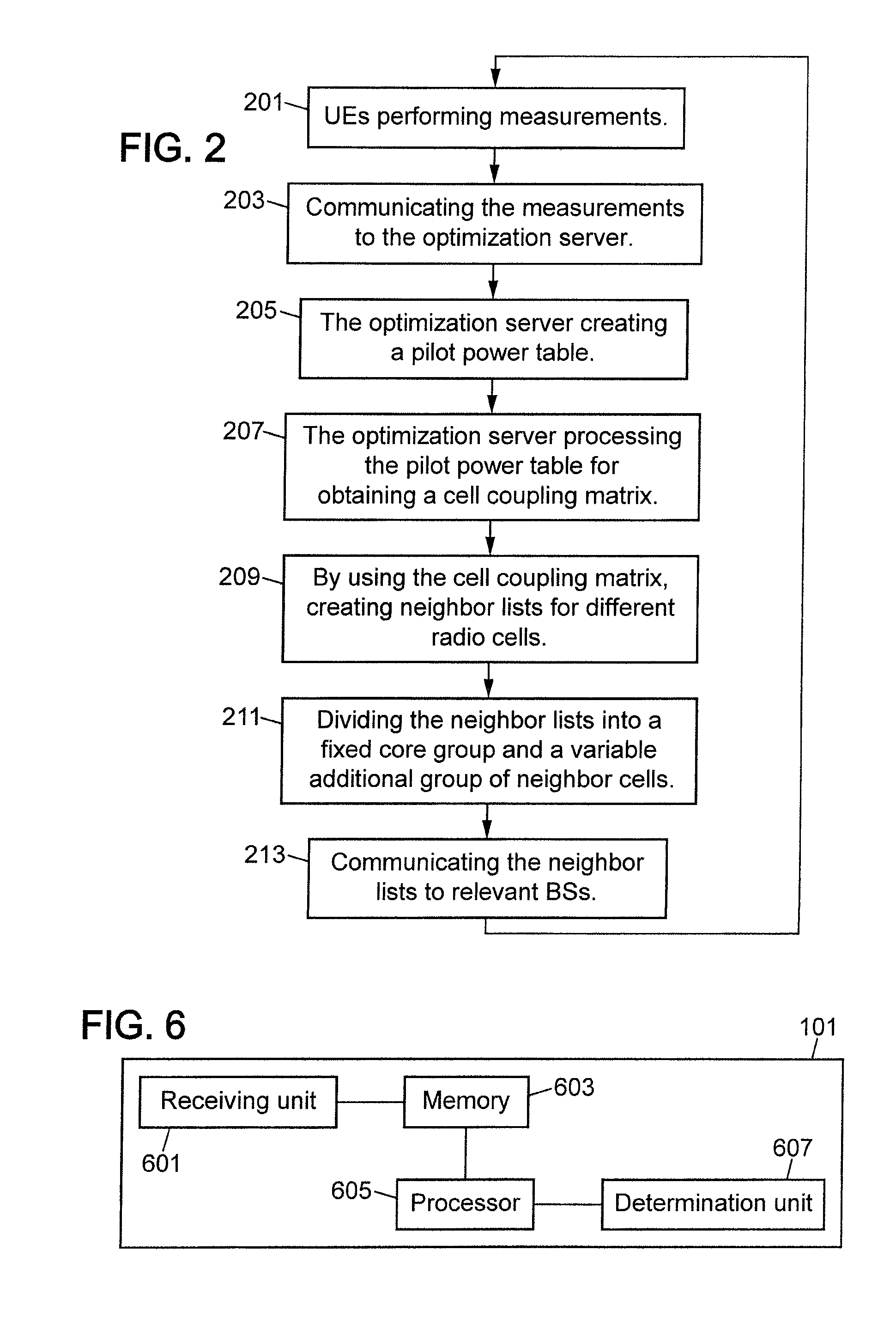
The invention is a new method for automatically creating neighbor lists in a radio communication network. The method uses data from user terminals to create a cell coupling matrix that indicates the radio coupling between different cells in the network. By calculating the coupling figure between a certain cell and another cell, a neighbor list can be obtained. This method offers the advantage of being cost-effective and based on real user traffic distribution, as it does not require drive testing. The invention also provides a computer program product and an optimization server for generating neighbor lists in a radio communication network.

Problems solved by technology

In many systems including universal mobile communication system (UMTS) and other systems based on code division multiple access (CDMA) scheme it is not practical for UEs to scan all possible channels or ID codes to find potential neighbors fast enough.
Current tuning methods require skilled experts to identify neighbors on a map, followed by a costly and time consuming tuning process involving drive testing.
Thus, the manual optimization is rather costly and time-consuming.
Furthermore, drive tests can never be fully representative of where users really are, since most calls are made indoors.
The optimization process gets even more complicated if wireless networks with many different protocols are organized to work together.
It will be too complex a task to manually identify and maintain neighbor lists between all these types of access.
Even though, after tuning, the final results are often acceptable, a significant effort is required.
Future wireless networks will be highly complex and interlinked, so manual methods may not be feasible.

Method used


Image

  • Optimizing neighbor lists
  • Optimizing neighbor lists
  • Optimizing neighbor lists

Examples


Embodiment Construction

[0028]One embodiment of the invention will next be described in the context of a cellular radio communication network, such as a UMTS. It is to be noted that the following exemplary embodiment is only illustrative and many alterations in the described embodiment are possible.

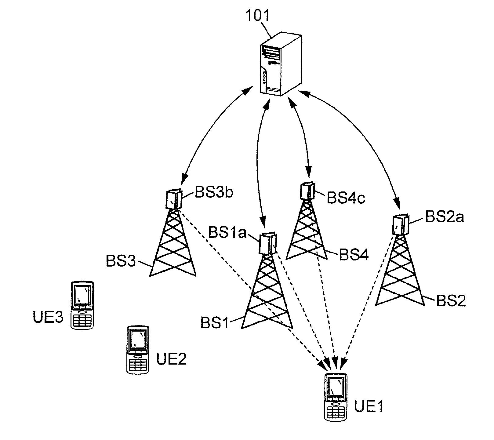
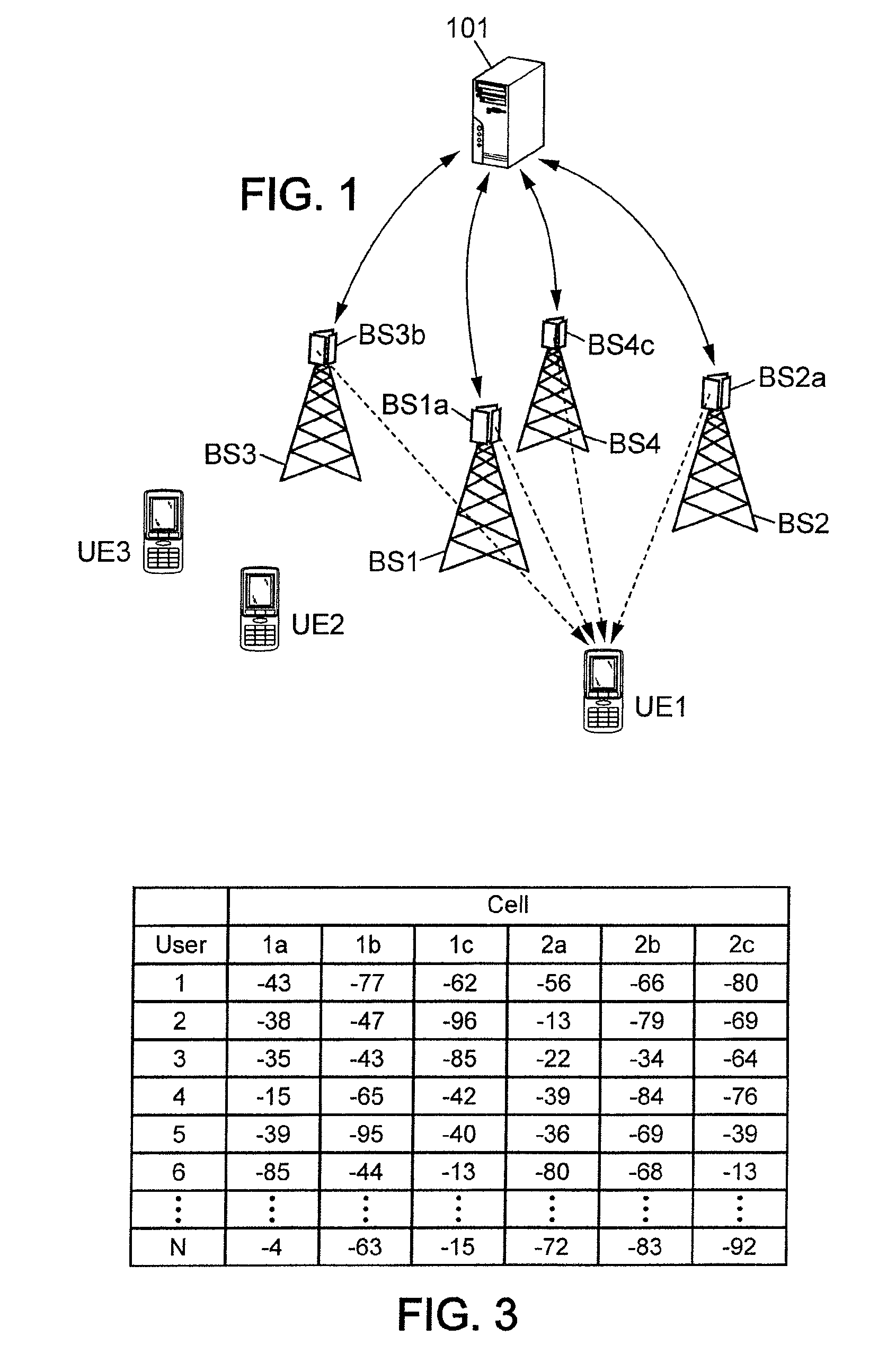
[0029]In FIG. 1 there are shown three UEs (UE1, UE2 and UE3) operating in a cellular communication network. There are also shown four BSs (BS1, BS2, BS3 and BS4), also known as node Bs in UMTS, serving the UEs by providing necessary radio channels. An optimization server 101 is also provided for generating neighbor lists in accordance with the invention as will be explained later in more detail. For simplicity only these units are shown in FIG. 1. Other elements that are not relevant for understanding the teachings of the present invention are not shown in FIG. 1, but a skilled person readily understands that a communication network also comprises other elements.

[0030]In FIG. 1, each BS site has three sector ant...


PUM


Abstract

The present invention relates to a method of generating neighbor lists in a radio communication network comprising user terminals and base stations defining sectored or omnidirectional radio cells, where communication between user terminals and base stations is arranged to take place over radio channels. The method comprises the steps of: (a) receiving radio channel measurements from at least some of the user terminals; (b) creating a first table by using the measurements received from the user terminals, the first table comprising for at least some of the user terminals the corresponding radio channel measurement in relation to different radio cells; (c) processing the first table to generate a cell coupling matrix indicative of a radio coupling figure between different pairs of cells in the network; and (d) for a certain cell obtaining a neighbor list by determining the radio channel neighbors to be the cells of which the coupling figure with the cell in question is greater than a given threshold.

Description

FIELD OF THE INVENTION[0001]The present invention relates to a method of optimizing neighbor lists maintained in base stations that operate in cellular radio communication networks. The invention equally relates to a corresponding computer program product and to an optimization server capable of carrying out the method.BACKGROUND OF THE INVENTION[0002]In radio communication networks each base station usually holds a neighbor list of nearby transceivers, to which user equipments (UEs) might hand over the ongoing radio connection as they move. Such a list may for instance indicate the most suitable radio channels that need to be considered when performing a handover.[0003]In many systems including universal mobile communication system (UMTS) and other systems based on code division multiple access (CDMA) scheme it is not practical for UEs to scan all possible channels or ID codes to find potential neighbors fast enough. Therefore, the neighbor list is downloaded from the serving trans...

Claims


Application Information

Patent Timeline
Patent Type & Authority Applications(United States)
IPC IPC(8): H04W24/02
CPCH04W24/00
Inventor ROBSON, JULIUS
Owner APPLE INC
Learn More