
Symbology for a flight display

a flight display and three-dimensional technology, applied in the field of flight displays for aircraft, can solve the problems of increasing pilot workload, reducing situational awareness, and inability to accurately interpret valuable data, so as to achieve sufficient separation from obstacles and enhance visibility within the display

Inactive Publication Date: 2009-10-22
AVIDYNE CORPORATION
View PDF5 Cites 20 Cited by
  • Summary
  • Abstract
  • Description
  • Claims
  • Application Information

AI Technical Summary

Benefits of technology

[0010]One exemplary embodiment includes a flight display having three-dimensional graphical representations of potential obstacles enclosed by an avoidance zone symbol. Advantageously, the pilot only needs to keep the total velocity vector aimed outside of the zone symbol to maintain sufficient separation from the obstacle. The avoidance zone symbol may be translucent, so that it does not block the view of terrain or other obstacles beyond it. The avoidance zone symbol may further be color-coded to enhance visibility within the display and to show the level of potential threat posed by a particular obstacle at the present time. In one example, the avoidance zone symbol may be displayed in cyan when the particular obstacle poses no threat. In another example, the avoidance zone symbol may be displayed in dim yellow when the particular obstacle does not pose an immediate threat. In still another example, the avoidance zone symbol may be displayed in red if the particular obstacle is within a specified time and / or distance from the aircraft's direction of travel. Additionally, the altitude needed to vertically clear the obstacle may display in red. In another example, the total velocity vector may overlay the avoidance zone symbol, gain a high contrast colored border, and / or begin to flash as the threat of the obstacle becomes more imminent. Additionally, an aural alert may accompany the visual warnings. In still another example, the red threats may display over the other attitude director indicator (ADI) instrumentation. At this point, avoiding the obstacle is of the highest priority to the pilot, even over monitoring the ADI instrumentation.

Problems solved by technology

The indicators are primarily mechanical, based on vacuum and pitot-static technology that is less accurate than similar electronic instruments.
While synthesizing this information may be a minor mental action in normal circumstances, a pilot inundated with time-sensitive information may face difficulty quickly interpreting valuable data under stressful emergency circumstances.
Even seemingly simple assessments like these increase pilot workload and diminish situational awareness.
Although more realistic, these images can be incredibly rich, presenting difficulty for the pilot in processing any overlaid information.

Method used


Image

  • Symbology for a flight display
  • Symbology for a flight display
  • Symbology for a flight display

Examples


Embodiment Construction

[0026]An improved system for integrating flight data into a three-dimensional electronic display is described. In the following description, for purposes of explanation, numerous specific details are set forth in order to provide a thorough understanding of the exemplary embodiments. It is apparent to one skilled in the art, however, that the present invention can be practiced without these specific details or with an equivalent arrangement. In some instances, well-known structures and devices are shown in block diagram form in order to avoid unnecessarily obscuring the preferred embodiment.

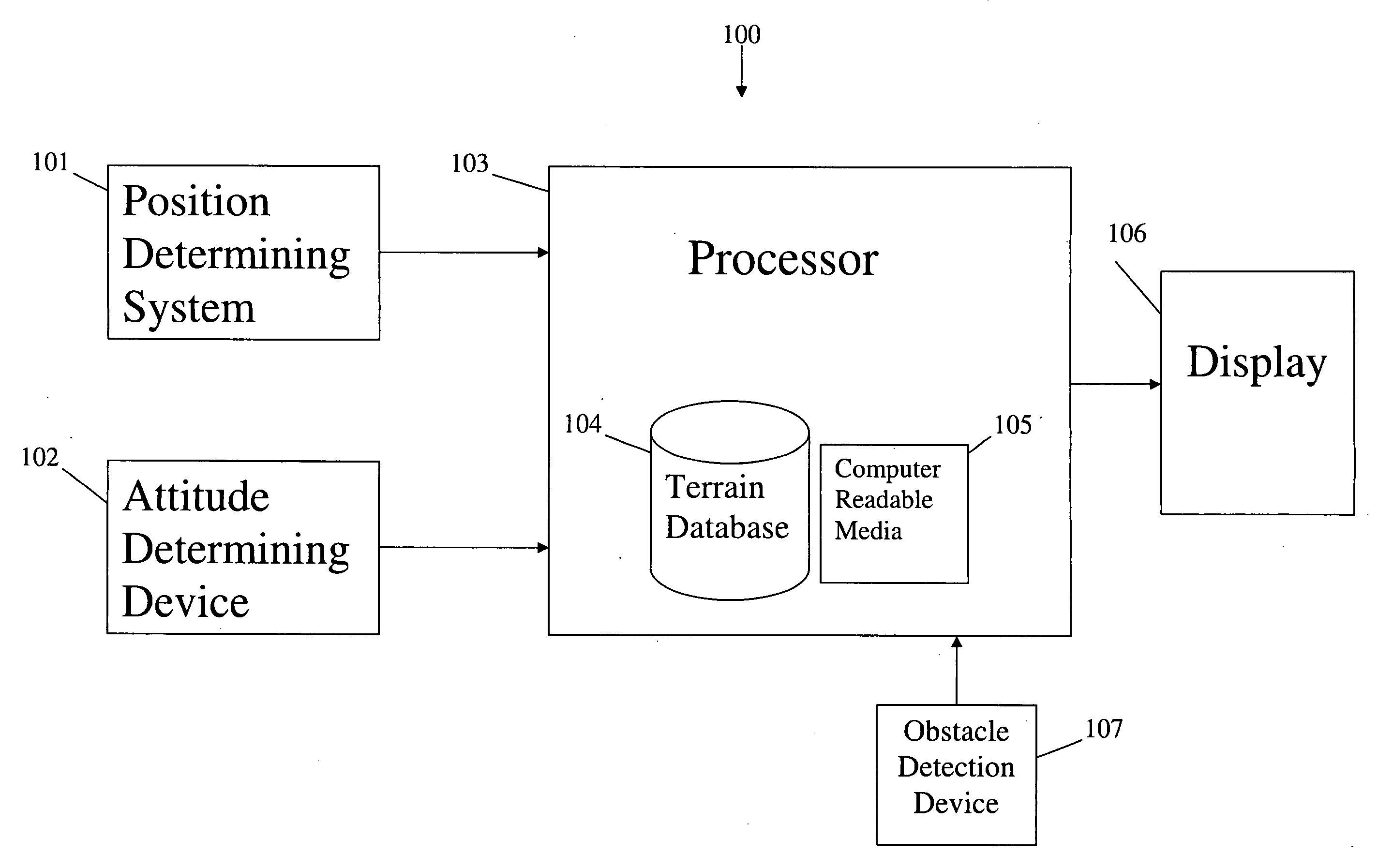
[0027]Referring now to the drawings, wherein like reference numerals designate identical or corresponding parts throughout the several views, and more particularly to FIG. 1, which shows primary flight display system 100 comprising position determining system 101, attitude determining device 102 and obstacle detection device 107, which may be operatively coupled to processor 103. Position determi...


PUM


Abstract

Flight display systems are provided that present a pilot with a three dimensional view of an area within a potential flight path of an aircraft. The three dimensional view may include representations of potential obstacles and avoidance zones surrounding the potential obstacles. The view may also include cardinal compass representation aligned with the visual horizon. Aircraft traffic obstacle symbols may be variable based on the type of aircraft represented.

Description

RELATED APPLICATION[0001]This application claims the benefit of U.S. Provisional Patent Application No. 60 / 996,392 which was filed on Nov. 15, 2007.BACKGROUND OF THE INVENTION[0002]1. Field of the Invention[0003]The present invention relates generally flight displays for aircraft. In particular, the present invention relates to symbology for a three-dimensional flight display.[0004]2. Description of Related Art[0005]A conventional primary flight display consists of an analog presentation of flight data distributed over several instruments: an attitude indicator, an altitude indicator, an airspeed indicator, a turn indicator, a heading indicator and a vertical speed indicator, for example. The indicators are primarily mechanical, based on vacuum and pitot-static technology that is less accurate than similar electronic instruments. The pilot must visually acquire, interpret and employ information from at least these six sources across the cockpit.[0006]Currently, the flight displays i...

Claims


Application Information

Patent Timeline
Patent Type & Authority Applications(United States)
IPC IPC(8): G08G5/04G06G7/76G08B21/00
CPCG08G5/0021G01C23/00
Inventor DIAS, ANTONIOJACOBSON, STEVEN W.
Owner AVIDYNE CORPORATION
Learn More