
Electro-Hydraulic Timed Angle Controlled Joint Simulation Torque Calibration, Certification and Analysis Device

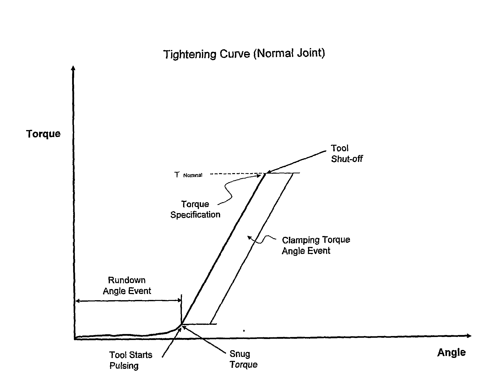
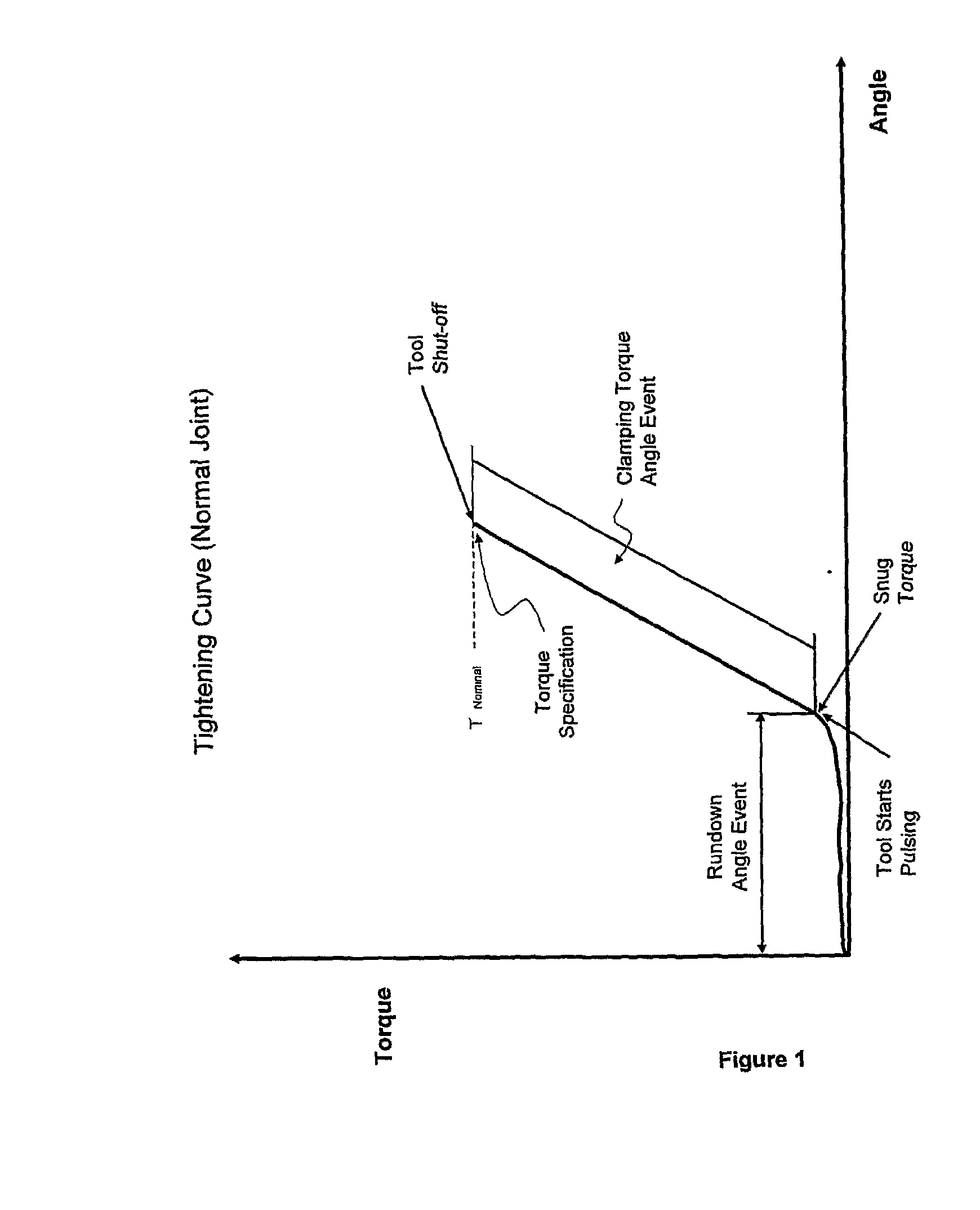
a technology of electric hydropower and joint simulator, applied in the direction of fluid pressure control, analog and hybrid computing, hardware monitoring, etc., can solve the problems of system inertia, joint simulators are capable of incorporating angle versus time,

Inactive Publication Date: 2009-10-22
HETZEL ADRIAN H
View PDF6 Cites 12 Cited by
  • Summary
  • Abstract
  • Description
  • Claims
  • Application Information

AI Technical Summary

Benefits of technology

[0006]An object of the present invention is to provide a joint simulator for testing a power tool, which overcomes the aforementioned shortcomings. The present joint simulator features a threaded shaft having an end engaged with a threaded opening in a piston, whereby rotating the shaft (for example with a power tool) causes the piston to slide. The shaft is supported by a housing, and the piston slides within a chamber formed in the housing. A hydraulic fluid fills a section of the chamber between the housing and the piston. Thus, as the shaft is rotated, the pressure of the hydraulic fluid against the piston increases. Pressure and relief valves regulate the flow of hydraulic fluid in and out of

Problems solved by technology

Further, when braking pads or discs are used to simulate a joint, the inertia of the system is often changed relative to the joint being simulated, which can lead to errors, particularly when testing an impulse power tool.
Still further, many prior art joint simulators employ in-line transducers and angle encoders, which change the inertia of the inertia of the system and lead to errors.
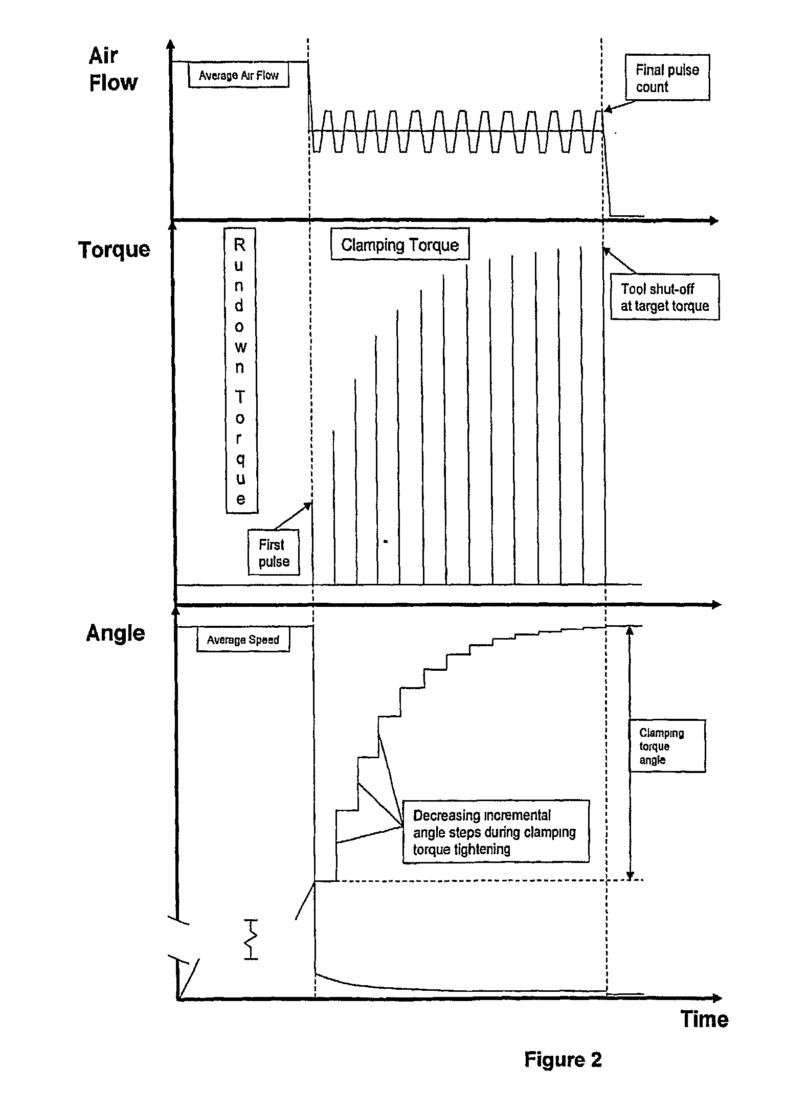
Few prior art joint simulators are capable of incorporating angle versus time into a process for joint simulation.

Method used


Image

  • Electro-Hydraulic Timed Angle Controlled Joint Simulation Torque Calibration, Certification and Analysis Device
  • Electro-Hydraulic Timed Angle Controlled Joint Simulation Torque Calibration, Certification and Analysis Device
  • Electro-Hydraulic Timed Angle Controlled Joint Simulation Torque Calibration, Certification and Analysis Device

Examples


Embodiment Construction

[0019]In conjunction with a traditional torque transducer used to measure the output of a power tool, this proposed process and apparatus adds a timed control of joint angle simulation to accurately reproduce joint characteristics as seen in the “real world” application of impulse power tools to assemble threaded joints. This invention is believed to be unique in that beyond simply using torque and angle to define the characteristics of joint, a very important previously excluded evaluation and simulation criteria, effective (real) tightening time versus angle, is now used to control the application of torque with respect to angle, to accurately reproduce a specific threaded joint on an assembled product. This additional time characteristic is critical for the proper evaluation of impulse power tools. Through variation of this timed control of joint angle simulation until the correct simulated joint characteristic is observed, allows all of the remaining types of power tools used to...


PUM


Abstract

A joint simulator is provided having a housing with a chamber, a piston, slidable within the chamber, and a shaft rotatable within the housing, the shaft having (i) an end configured to engage a power tool to be tested, and (ii) a threaded end engaged with the piston, whereby rotating the shaft causes the piston to slide within the chamber Hydraulic fluid fills a section of the chamber formed by a side of the piston and the housing, and computer software controlled pressure and relief valves are actuated to regulate the flow of hydraulic fluid in the chamber, to achieve target pressures. The pressure of the hydraulic fluid creates resistance to rotation of the shaft, thereby increasing the torque relative to the angular increase on the shaft and / or relative to time. The joint simulator is provided with means to determine the angular displacement and torque applied to the shaft;

Description

TECHNICAL FIELD[0001]This invention is intended to provide a new process and apparatus for the calibration, testing and analysis of impulse power tools used to tighten threaded fasteners.BACKGROUND ART[0002]During a typical clamping phase of a tightening event, the torque applied to the fastener increases as the friction between the threads of the fastener and the threaded body into which the fastener is being screwed increases. The tightening event may be described as an angular increase in the orientation of the fastener.[0003]Prior art joint simulators typically rely upon a frictional brake to increase torque, while a power tool is being tested. In Crane et at., U.S. Pat. No. 6,202,028 B1, a computer controls the magnitude of the braking torque applied to a shaft, to simulate the increase in torque that occurs when a joint is being tightened. Chiapuzzi et al., U.S. Pat. No. 6,718,831 B2, disclose a screwer test bench in which a pressurized fluid is used to control a frictional br...

Claims


Application Information

Patent Timeline
IPC IPC(8): G06F15/00G06G7/64
CPCG05D16/2053G01L25/003
Inventor HETZEL, ADRIAN H.
Owner HETZEL ADRIAN H
Learn More