Flow diagnosis apparatus for fuel vapor purge system

Inactive Publication Date: 2009-10-29
DENSO CORP
View PDF16 Cites 53 Cited by
  • Summary
  • Abstract
  • Description
  • Claims
  • Application Information

AI Technical Summary

Problems solved by technology

When the fuel vapor passage is clogged with a foreign object (e.g., debris, dusts or the like), the fuel vapor in the fuel tank cannot be purged into the air intake system.
Therefore, even when the behavior of the pressure, which is sensed with the pressure sensor during the period of introducing the negative pressure into the fuel vapor system, is monitored, it is difficult to distinguish be

Method used


Image

  • Flow diagnosis apparatus for fuel vapor purge system
  • Flow diagnosis apparatus for fuel vapor purge system
  • Flow diagnosis apparatus for fuel vapor purge system

Examples


first embodiment

[0029]A first embodiment of the present invention will be described with reference to FIGS. 1 to 10.

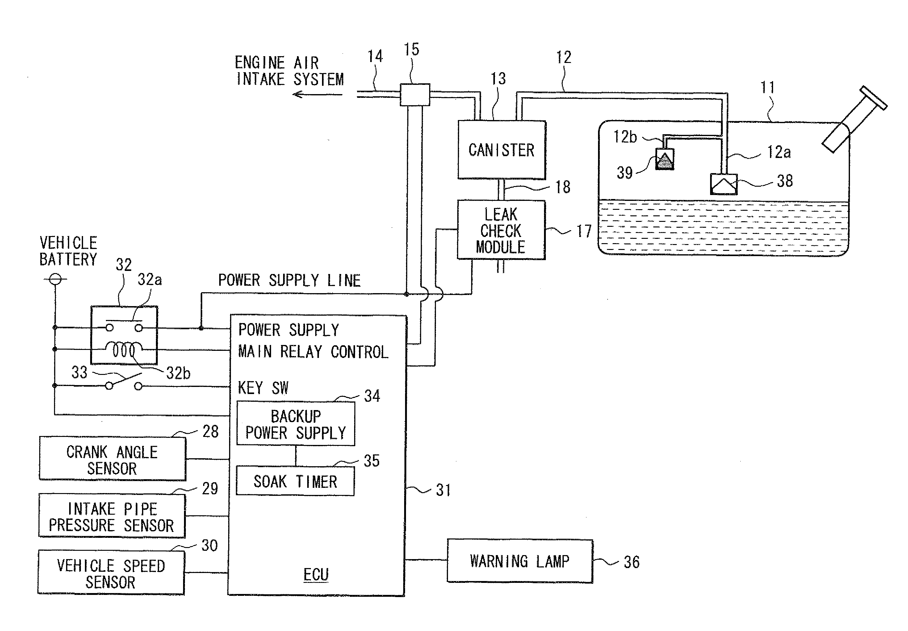
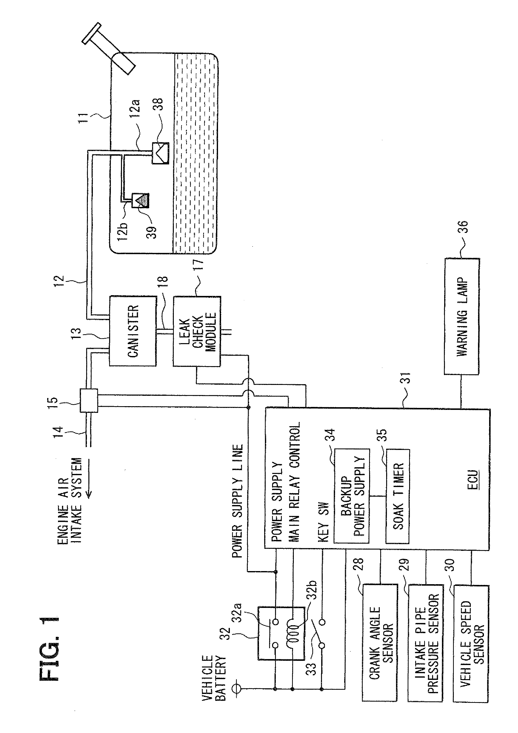
[0030]First, a structure of a fuel vapor purge system (an evaporative emission purge system) of the present embodiment will be schematically described with reference to FIG. 1.

[0031]A canister 13 is connected to a fuel tank 11 through a fuel vapor leading passage (a part of a fuel vapor passage) 12. An adsorbent material (not shown), such as an activated carbon material, is received in the canister 13 to adsorb the fuel vapor (fuel evaporative emissions).

[0032]A fuel vapor purge passage (another part of the fuel vapor passage) 14 is provided between the canister 13 and an air intake system of an internal combustion engine to purge the fuel vapor, which has been adsorbed on the adsorbent material in the canister 13, into the air intake system. A purge control valve 15 is installed in the purge passage 14 to control the purge flow quantity of the fuel vapor in the purge passage 14. The ...

second embodiment

[0086]A second embodiment of the present invention will be described with reference to FIGS. 11 to 13. In the following description, components as well as steps similar to those of the first embodiment will not be described for the sake of the simplicity, and differences, which are different from those of the first embodiment, will be mainly discussed.

[0087]In the second embodiment, the ECU 31 executes the respective routines shown in FIGS. 11 to 13 to determine whether the fuel level in the fuel tank 11 is the full level based on the sensed pressure behavior after the negative pressure introduction (the behavior of the internal pressure of the fuel vapor system, which is sensed with the pressure sensor 26 in the sealed state of the fuel vapor system after the introduction of the negative pressure into the fuel vapor system). Thereafter, when it is determined that the fuel level in the fuel tank 11 is the full level, the execution of the post-depressurization period flow diagnosis i...


PUM


Abstract

A pressure sensor senses a pressure of a fuel vapor system at a fuel vapor passage. An electronic control unit executes a post-depressurization period flow diagnosis to determine whether the fuel vapor passage is clogged based on a behavior of the pressure in the fuel vapor system, which is sensed with the pressure sensor in a sealed state of the fuel vapor system after introduction of a negative pressure into the fuel vapor system.

Description

CROSS REFERENCE TO RELATED APPLICATION[0001]This application is based on and incorporates herein by reference Japanese Patent Application No. 2008-113365 filed on Apr. 24, 2008.BACKGROUND OF THE INVENTION[0002]1. Field of the Invention[0003]The present invention relates to a flow diagnosis apparatus for a fuel vapor purge system.[0004]2. Description of Related Art[0005]In a previously proposed fuel vapor purge system, fuel vapor, which is generated in a fuel tank of a vehicle, is adsorbed to an adsorbent material received in a canister to limit leakage of the fuel vapor from the fuel tank to the surrounding atmosphere. Then, the fuel vapor, which is adsorbed to the adsorbent material in the canister, is desorbed from the adsorbent material and is purged into an air intake system of an internal combustion engine, which supplies fresh air to combustion chambers of the internal combustion engine. The purging of the fuel vapor is accomplished by action of a negative pressure in the air ...

Claims


Application Information

Patent Timeline
IPC IPC(8): G01M3/28G01M15/02G01F23/00
CPCG01F22/02F02M25/0818
Inventor MAEGAWA, YOSHINORI
Owner DENSO CORP
Why Eureka
Try Eureka