Cylinder head gasket

a technology of cylinder head and gasket, which is applied in the direction of engine seals, sealing arrangements, machines/engines, etc., can solve the problems of reducing the spring-back potential of the sealing bead of one functional layer, and allowing a smaller range of sealing

Inactive Publication Date: 2009-10-29
ELRINGKLINGER AG
View PDF16 Cites 9 Cited by
  • Summary
  • Abstract
  • Description
  • Claims
  • Application Information

AI Technical Summary

Benefits of technology

[0015]In accordance with a first alternative, the inner layer has in the region of its ring zone a cross-sectional deformation which increases its flexural rigidity. Such a cross-sectional deformation can be achieved in a particularly simple way by the inner layer being subjected to an embossing operation.
[0019]In a cylinder head gasket according to the invention, the two or three functional layers form together with the inner layer a set of layers whose side facing the cylinder head or the engine block, when the cylinder head gasket is installed, is formed by a respective functional layer. It is recommended that these two functional layers be so designed that their sealing beads project in the direction towards the interior of the set of layers, so that the bead feet of the sealing beads of these two functional layers face the sealing surfaces of the cylinder head and the engine block. The risk of indentations or increased fictional wear in or on these sealing surfaces is thereby minimized, namely in comparison with cylinder head gaskets in which the crests of the sealing beads of the outer functional layers of the set of layers face the sealing surfaces of cylinder head and engine block.

Problems solved by technology

The spring-back potential of the sealing bead of the one functional layer is reduced by this deformation of the carrier sheet as pressing against the carrier sheet with a specific surface pressure that is required for a reliable sealing effect can no longer be brought about by the sealing bead on account of the arching of the carrier sheet when the width or breadth of the sealing gap between cylinder head and engine block increases over time during operation of the engine.
The known cylinder head gaskets of the kind defined at the outset, therefore, have the disadvantage of allowing a smaller range of sealing gap dynamics if sealing against issue of combustion gases is to be reliably effected around a combustion chamber opening.

Method used


Image

  • Cylinder head gasket
  • Cylinder head gasket
  • Cylinder head gasket

Examples


Embodiment Construction

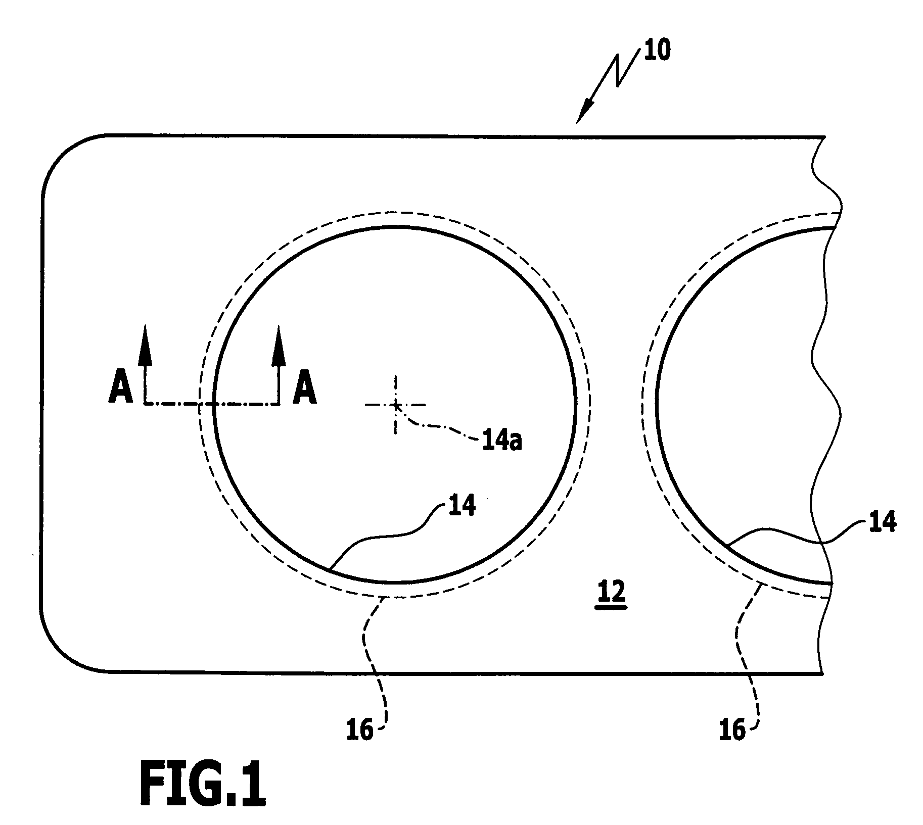
[0025]FIG. 1 shows part of a cylinder head gasket 10 according to the invention for a multicylinder engine, which is formed by a gasket plate 12 with a plurality of combustion chamber openings 14. In one of these combustion chamber openings 14, its center or axis has been designated 14a. As will be apparent from the following, the gasket plate 12 is made up of a plurality of sheet metal layers placed one on the other, some of which are provided with sealing beads designated 16 in FIG. 1, which surround the combustion chamber openings 14 and extend concentrically with the axis 14a of the respective combustion chamber opening. In FIG. 1, the sealing beads 16 are indicated only in broken lines because an upper, in accordance with FIG. 1, layer of the gasket plate 12 may be a smooth cover layer without any sealing beads.

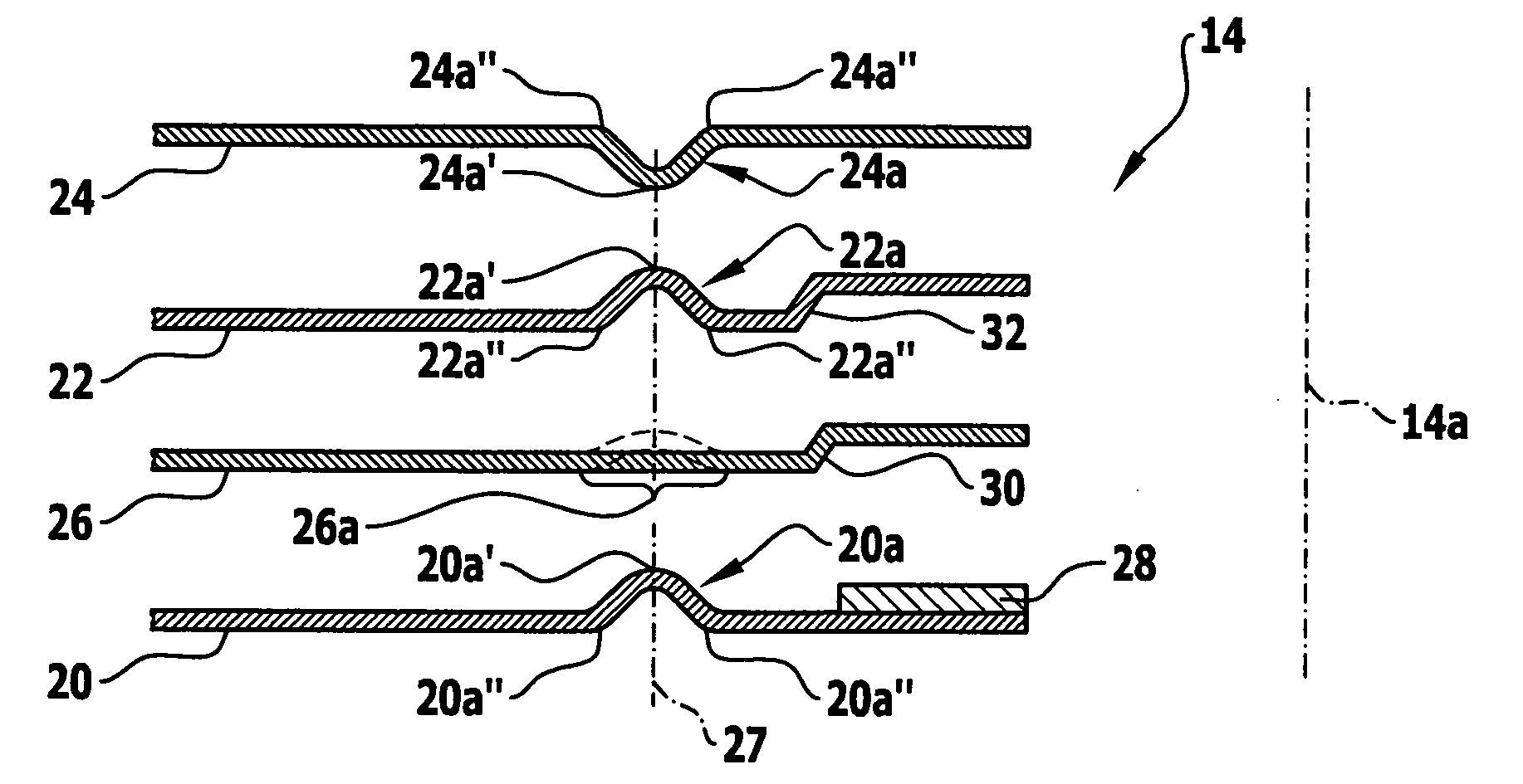
[0026]The part of a known cylinder head gasket represented in section in FIG. 2 has four sheet metal layers arranged one on the other, namely three functional layers and...


PUM


Abstract

Cylinder head gasket with a gasket plate comprising a plurality of sheet metal layers and at least one combustion chamber opening, an inner layer being arranged in the gasket plate directly between two functional layers having sealing beads arranged one over the other, which enclose the combustion chamber opening and have bead feet lying in the planes of the functional layers and bead crests with which sealing beads of the two functional layers all project over the functional layers in a first direction extending perpendicularly to the gasket plane, at least one ring zone of the inner layer being clamped between the bead feet of the one functional layer and at least one bead crest of the other functional layer when the gasket is pressed; to minimize arching of this ring zone, it is stiffened and / or those ring zone regions against which at least one bead crest of one functional layer lies when the gasket is pressed are supported by bead feet of the other functional layer.

Description

[0001]The present disclosure relates to the subject matter disclosed in German application number 10 2008 020 277.0 of Apr. 23, 2008, which is incorporated herein by reference in its entirety and for all purposes.BACKGROUND OF THE INVENTION[0002]The invention relates to a cylinder head gasket with a gasket plate comprising a plurality of sheet metal layers and at least one combustion chamber opening and defining a gasket plane, an inner layer being arranged in the gasket plate directly between two functional layers having sealing beads arranged one over the other, which enclose the combustion chamber opening and have bead feet lying in the planes of the functional layers and bead crests with which the sealing beads of the two functional layers all project over the functional layers in a first direction extending perpendicularly to the gasket plane, at least one ring zone of the inner layer lying between the sealing beads being clamped between the bead feet of the one functional laye...

Claims


Application Information

Patent Timeline
Patent Type & Authority Applications(United States)
IPC IPC(8): F02F11/00
CPCF16J15/0825
Inventor SCHMUCKER, FRANK
Owner ELRINGKLINGER AG
Why Eureka
Try Eureka