Small Aperture Interrogator Antenna System Employing Sum Difference Azimuth Discrimination Techniques

an interrogator antenna and sum difference azimuth discrimination technology, applied in the field of radio frequency (rf) antennas, can solve the problem of grating lobes and achieve the effect of cost saving

Inactive Publication Date: 2009-10-29
RAYTHEON CO
View PDF5 Cites 83 Cited by
  • Summary
  • Abstract
  • Description
  • Claims
  • Application Information

AI Technical Summary

Benefits of technology

[0016]Furthermore, ease of manufacture of horn type antennas, as compared to manufacturing techniques required for prior art interrogator array systems, provides cost savings making combat identification available to more users. Economies of scale afforded by the ease of manufacture of the three horn interrog

Problems solved by technology

The use of horn antennas as opposed to linear antenna elements in an array configuration results in a number of grating lobes (unwanted and undesired) in t

Method used


Image

  • Small Aperture Interrogator Antenna System Employing Sum Difference Azimuth Discrimination Techniques
  • Small Aperture Interrogator Antenna System Employing Sum Difference Azimuth Discrimination Techniques
  • Small Aperture Interrogator Antenna System Employing Sum Difference Azimuth Discrimination Techniques

Examples


Embodiment Construction

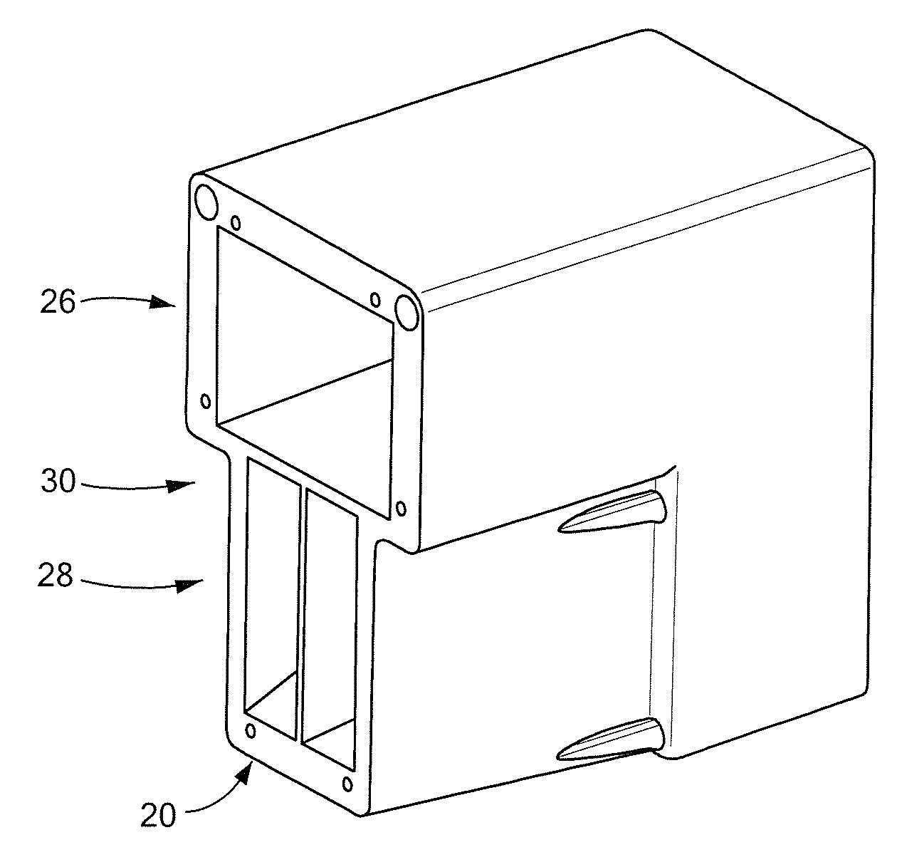
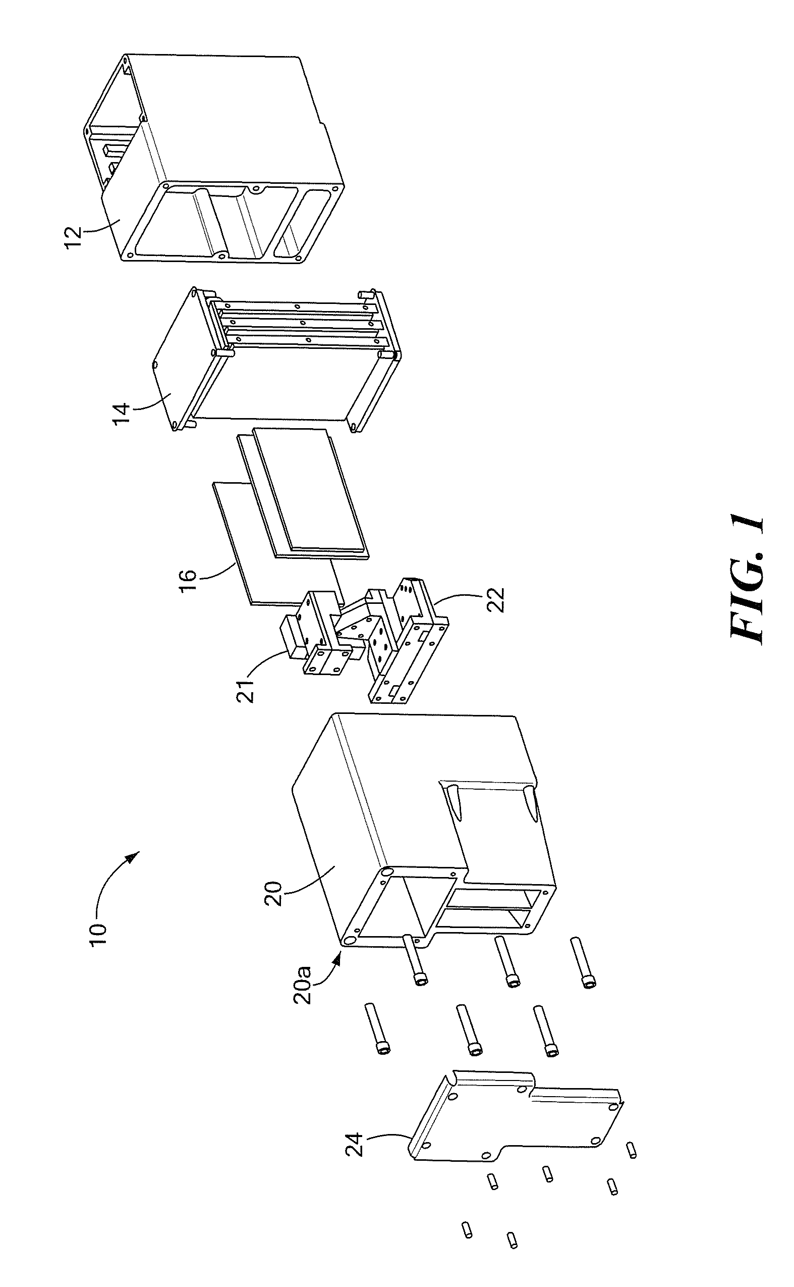
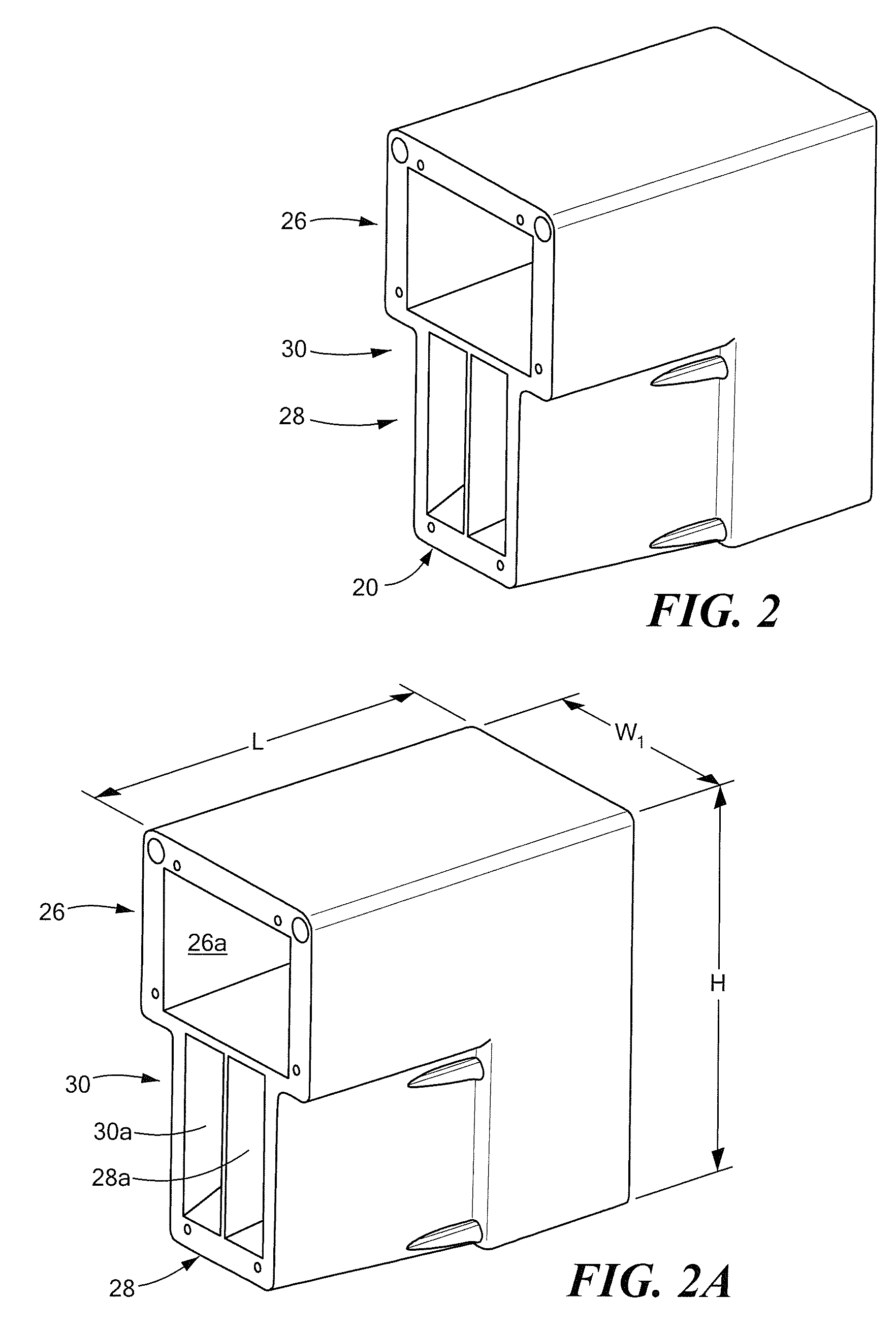
[0036]Referring now to FIG. 1, a light weight vehicle Crew Served Combat ID (CSCID) 10 includes a chassis 12 having a miniaturized control interface electronics module (MCM) 14 coupled thereto. The MCM 14 directs a transceiver, 16, an antenna matching network 21, 22, a horn antenna assembly 20, and a polarizer / cover 24 to transmit either a sum pattern by directing the transceiver output to a sum port of the matching network 21, 22 or a difference pattern, by directing the transceiver output to a difference port of the matching network 21,22. In one particular embodiment, the output of transceiver 16 is coupled to the matching network sum port via a direct connection between the transceiver and the sum horn. The sum and difference patterns are sequenced with a specific time duration for each which is controlled by the MCM 14.

[0037]Transceiver 16 is coupled to the MCM 14 and horn antenna assembly 20 is coupled to transmit signals to / from MCM 14 and antenna matching networks 21, 22 are...


PUM


Abstract

An antenna system comprising a first antenna corresponding to a horn antenna, a second antenna corresponding to a horn antenna disposed such that the E-plane of the second antenna is co-planar with the E-plane of the first antenna an such that an aperture of the first antenna and an aperture of the second antenna are substantially in a common plane; and a third antenna corresponding to a horn antenna disposed such that the E-plane of the third antenna is substantially co-planar with the E-plane of the first antenna and such that an aperture of said third antenna is substantially in the same plane as the aperture of the first and second antennas and wherein the second and third antennas are canted toward each other.

Description

RELATED APPLICATIONS[0001]This application claims the benefit of U.S. Provisional Application No. 61 / 048,760 filed Apr. 29, 2008 under the provisions of 35 U.S.C. §119(e) which application is hereby incorporated herein by reference in its entirety.FIELD OF THE INVENTION[0002]This invention relates to radio frequency (RF) antennas and more particularly to array antenna systems capable of operation in the milli-meter wave (mmW) frequency range.BACKGROUND OF THE INVENTION[0003]As is known in the art, combat identificaton (or CID), is the process of attaining an accurate characterization of targeted and detected objects in a battlespace. Depending upon the situation, such a characterization may be limited to identification of an object with an identifier such as “friend,”“enemy,” or “neutral.” In other situations, other characterizations may be required, including, but not limited to, class, type, nationality, and mission configuration may be used along with appropriate identifiers.[000...

Claims


Application Information

Patent Timeline
IPC IPC(8): H01Q13/02
CPCG01S13/762G01S13/78H01Q25/02H01Q13/02H01Q1/27
Inventor TAHMISIAN, JR., THEODORE N.HALL, CHARLES A.
Owner RAYTHEON CO
Why Eureka
Try Eureka