Remote control transmitter

a transmitter and remote control technology, applied in the field of remote control transmitters, can solve the problems of slow detection of motion operation for absolute direction or rotation around absolute direction, inability to accurately detect absolute direction and angle of rotation around an axis in an absolute direction using the geomagnetic field sensor, etc., and achieve the effect of simple structur

Inactive Publication Date: 2009-10-29
SMK CORP
View PDF8 Cites 22 Cited by
  • Summary
  • Abstract
  • Description
  • Claims
  • Application Information

AI Technical Summary

Benefits of technology

[0013]The present invention is the result of contemplation on these conventional problem areas, and the object thereof is to provide a remote control transmitter able to dete

Problems solved by technology

However, these motion sensors, such as acceleration sensors and gyroscopes, detect only the direction of relative motion of the case or the direction of rotation of the case, and do not detect the absolute direction of motion in the vertical direction or horizontal direction.
Thus, there is a problem in that different control data could be outputted with the same motion operation by the user depending on the orientation of the case or the direction in which the user grasps the case.
However, in this conventional remote control transmitter wherein the calculation is performed by subtracting the gravity vector component from the detected value by the acceleration sensor, it is necessary to perform complicated calculations to correct the gravity vector component each time a motion operation is detected.
Because of this, the detection of a motion operation for an absolute direction or a rotation around an absolute direction is slow, requiring the use of a microprocessor with sophisticated processing capabilities for the calculation.
Notably, even when an absolute direction is obtained for the horizontal direction using a magnetic sensor, the geomagnetic field sensor is not attached in the case so as to always detect the geomagnetic fie

Method used


Image

  • Remote control transmitter
  • Remote control transmitter
  • Remote control transmitter

Examples


Embodiment Construction

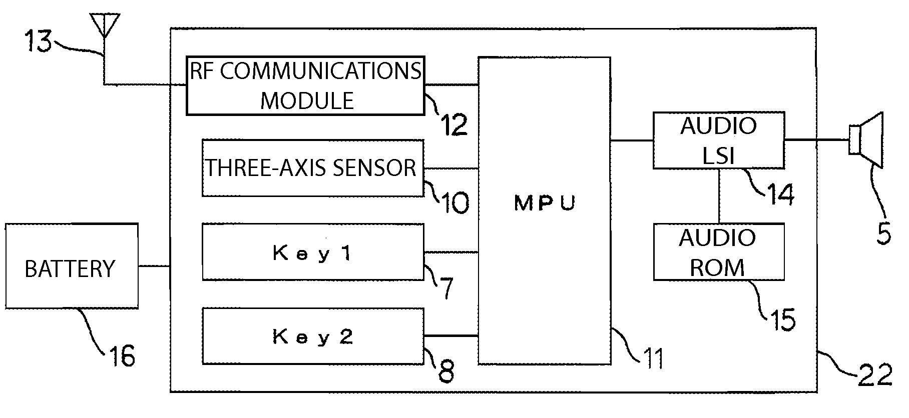
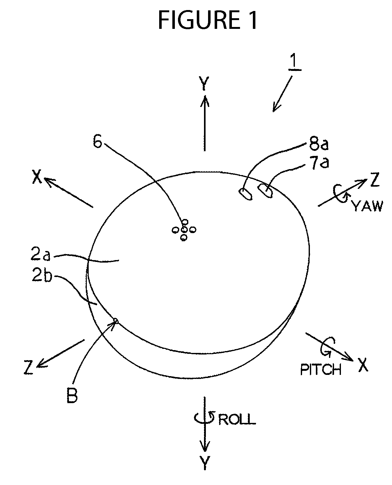
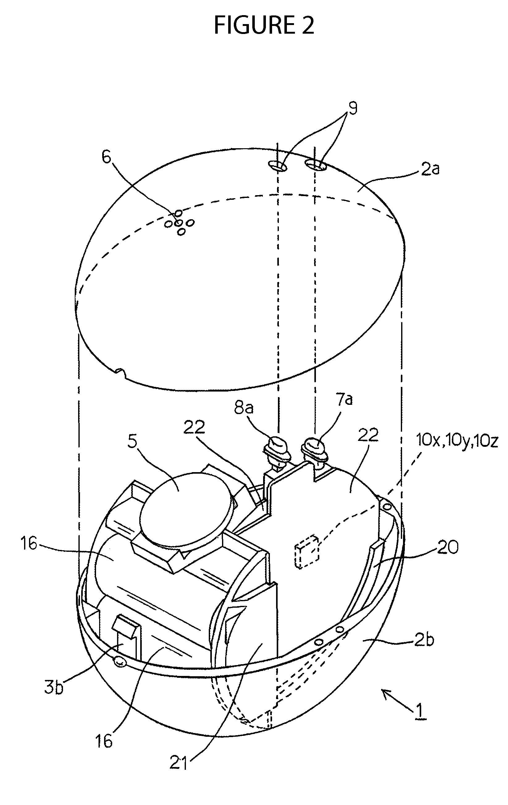
[0059]A listing of some of the reference numerals and letters that are used in the drawings, together with descriptions of the corresponding elements, is provided below:[0060]1, 30: Remote Control Transmitter[0061]2: Case[0062]5: Speaker[0063]7: Push Switch[0064]7a: Operating Button[0065]8: Push Switch[0066]8a: Operating Button[0067]10: Three-Axis Acceleration Sensor (Motion Sensor)[0068]10x: X Direction Sensor (X Direction Acceleration Sensor)[0069]10y: Y Direction Sensor (Y Direction Acceleration Sensor)[0070]10z: Z Direction Sensor (Acceleration Sensor for Detecting Acceleration in the Vertical Direction)[0071]11: MPU (Control Circuit Element)[0072]12: RF Communications Module[0073]16: Battery[0074]C: Center of Curvature[0075]G: Remote Control Transmitter Center of Gravity[0076]B: Stable Portion

[0077]A remote control transmitter 1 as set forth in one example of an embodiment of the present invention will be explained below, with reference to FIG. 1 through FIG. 6.

[0078]As is illu...


PUM


Abstract

A remote control transmitter detects motion in a specific direction or in a rotational direction around a specific axis: The transmitter includes a battery placed on a bottom surface side within a case containing circuitry of the transmitter. The bottom surface side has a convex surface, with a center of curvature C coincident in the upward direction of the force of gravity above a center of gravity G of the transmitter. When placed on a flat surface, the transmitter assumes a stable orientation such that when the transmitter is grasped in order to perform a motion-based operation, it can be can be assumed that the vertical direction is the direction of the line joining the center of curvature C of the stable portion to the center of mass G, as an absolute direction for reference in detecting the motion operation.

Description

CROSS REFERENCE TO RELATED APPLICATION[0001]This application claims the benefit under 35 U.S.C. §119 of Japanese Patent Application No. 2008-113070, filed on Apr. 23, 2008, which is hereby incorporated by reference herein in its entirety.FIELD OF INVENTION[0002]The present invention relates to a remote control transmitter for controlling remotely a device to be controlled, such as a household electronic device, and more specifically, to a remote control transmitter performing a specific action on the device to be controlled via a shaking or rotating operation performed on the remote control transmitter.BACKGROUND OF THE INVENTION[0003]Conventionally, remote control transmitters have been provided with a plurality of operating switches corresponding to individual control data for controlling remotely devices to be controlled. In addition, remote control transmitters have been provided for controlling remotely a device in accordance with a shaking or rotating motion operation on the r...

Claims


Application Information

Patent Timeline
IPC IPC(8): G06F3/033G06F3/0346G08B21/00H03K17/94H04N5/00H04Q9/00
CPCG08C17/02H01H35/14H01H9/0235G08C2201/32
Inventor OOTSUKA, KENJI
Owner SMK CORP
Why Eureka
Try Eureka