Method for driving plasma display panel

a technology of plasma display panel and drive mechanism, which is applied in the direction of instruments, television systems, static indicating devices, etc., can solve the problems of difficult discharge of discharge cells, and achieve the effects of increasing discharge strength, reducing power consumption, and reducing power consumption

Inactive Publication Date: 2009-10-29
PANASONIC CORP
View PDF2 Cites 7 Cited by
  • Summary
  • Abstract
  • Description
  • Claims
  • Application Information

AI Technical Summary

Benefits of technology

[0011]Therefore, the present invention has been made in view of the above problems, and it is an object of the present invention to provide a method for driving a Plasma Display Panel (PDP) which can reduce power consumption without causing display malfunction or reducing image quality.
[0014]When the input of an image signal is stopped or when an input image signal enters an entirely-black image state, the application of a drive pulse for driving the PDP is stopped to reduce power consumption. Here, when the input of an image signal is resumed or when the image signal returns from the entirely-black image to a normal image state, the absolute value of a peak potential of the drive pulse or the pulse width of the drive pulse is increased to a normal absolute value or a normal pulse width to increase the strength of discharge until a predetermined period elapses after resumption of image signal input. That is, after the application of the drive pulse is stopped, the number of priming particles remaining in the discharge cell decreases, thereby bringing the discharge cell into a state in which it is difficult to generate discharges. Thus, immediately after the input of an image signal is resumed or the image signal returns to a normal image state, the absolute value of a peak potential of each of the various drive pulses or the pulse width of each of the various drive pulses is increased during a predetermined period to increase the strength of discharge so that discharges are generated even though the number of priming particles remaining in the discharge cell is small. Due to discharges generated during this predetermined period, the number of priming particles is increased so that it is easy to generate discharges in the discharge cell and thus the absolute value of the peak potential of each of the various drive pulses or the pulse width of each of the various drive pulses is returned to a normal absolute value or a normal pulse width. According to this method, even though the application of the drive pulse is resumed after the application of the drive pulse is stopped to reduce power consumption, stable discharges can be generated immediately after the application of the drive pulse is resumed, and it is thus possible to reduce power consumption without causing display malfunction or reducing image quality.

Problems solved by technology

That is, after the application of the drive pulse is stopped, the number of priming particles remaining in the discharge cell decreases, thereby bringing the discharge cell into a state in which it is difficult to generate discharges.

Method used


Image

  • Method for driving plasma display panel
  • Method for driving plasma display panel
  • Method for driving plasma display panel

Examples


Embodiment Construction

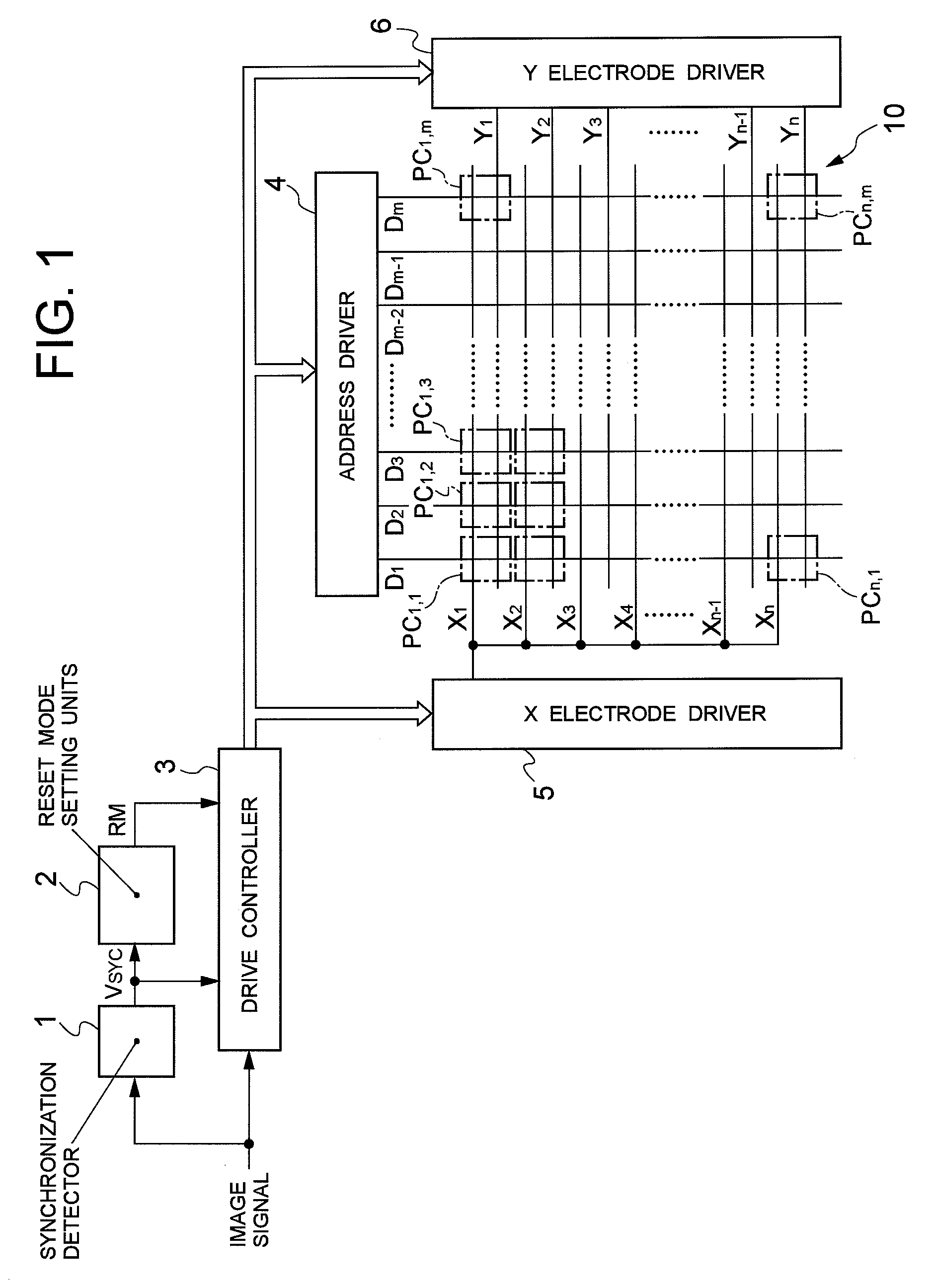
[0034]FIG. 1 illustrates a configuration of a plasma display device that drives a Plasma Display Panel (PDP) according to a drive method according to the invention.

[0035]As shown in FIG. 1, the plasma display device includes a PDP 10 that includes a front substrate (not shown) serving as a display surface and a rear substrate (not shown) with discharge gases being sealed in discharge spaces defined between the front and rear substrates. Row electrodes X1 to Xn and row electrodes Y1 to Yn are alternately arranged, extending in a horizontal direction of the 2D display screen, on the front substrate. A pair of neighboring row electrodes X and Y serves as one display line in the 2D display screen. Column electrodes D1 to Dm are arranged, extending in a vertical direction of the 2D display screen, on the rear substrate such that the column electrodes D1 to Dm cross the row electrodes X1 to Xn and Y1 to Yn as shown in FIG. 1. Here, one column electrode D serves as one column of the 2D dis...


PUM


Abstract

A plasma display device and a method for driving a Plasma Display Panel (PDP), which can reduce power consumption without causing display malfunction or reducing image quality, are provided. When the input of an image signal is stopped or when an input image signal is in an entirely-black image state, the application of a drive pulse for driving the PDP is stopped. Here, when the input of the image signal is resumed or when the input image signal switches from the entirely-black image state to a normal image state, the absolute value of a peak potential of the drive pulse or the pulse width thereof is increased to increase the strength of discharge until a predetermined period elapses after the resumption or switching and then the absolute value of a peak potential of the drive pulse or the pulse width is returned to a normal absolute value or a normal pulse width.

Description

BACKGROUND OF THE INVENTION[0001]1. Field of the Invention[0002]The present invention relates to a method for driving a plasma display panel.[0003]2. Description of the Related Art[0004]Currently, a plasma display device including a Plasma Display Panel (PDP), in which discharge cells corresponding to pixels are arranged in a matrix, is commercially available as a thin large-screen display device.[0005]The PDP includes a front substrate serving as a display surface and a rear substrate with discharge gases being sealed in discharge spaces defined between the front and rear substrates. Pairs of row electrodes X and Y, which serve respectively as display lines of one screen, are arranged on the front substrate. Column electrodes are arranged, extending in a direction crossing the pairs of row electrodes, on the rear substrate. Discharge cells, each serving as a pixel, are formed in respective intersection portions between the pairs of row electrodes X and Y and the column electrodes.[...

Claims


Application Information

Patent Timeline
Patent Type & Authority Applications(United States)
IPC IPC(8): G09G5/08G09G3/28G09G3/288G09G3/20G09G3/291G09G3/292G09G3/296G09G3/298H04N5/66
CPCG09G3/2927G09G3/293G09G2360/16G09G2330/022G09G2320/0238
Inventor KITAGAWA, MITSUSHIISHIZUKA, MITSUHIROYAHAGI, KAZUO
Owner PANASONIC CORP
Why Eureka
Try Eureka