Thermoacoustic device

a thermoacoustic device and carbon nanotube technology, applied in electrothermic-effect transistors, mechanical vibration separation, sonic/ultrasonic/infrasonic transmission, etc., can solve the problems of sound wave generation, thermophone adopting platinum strips, listened to open air, and extremely weak sound

Active Publication Date: 2009-10-29
BEIJING FUNATE INNOVATION TECH +1
View PDF25 Cites 20 Cited by
  • Summary
  • Abstract
  • Description
  • Claims
  • Application Information

AI Technical Summary

Problems solved by technology

However, the structure of the electric-powered loudspeaker 100 is dependent on magnetic fields and often weighty magnets.
The heating of the medium causes thermal expansion and produces pressure waves in the surrounding medium, resulting in sound wave generation.
However, the thermophone adopting the platinum strip, listened to the open air, sounds extremely weak because the heat capacity per unit area of the platinum strip is too high.

Method used


Image

  • Thermoacoustic device
  • Thermoacoustic device
  • Thermoacoustic device

Examples


Embodiment Construction

[0034]Reference will now be made to the drawings to describe, in detail, embodiments of the present thermoacoustic device and method for generating sound waves.

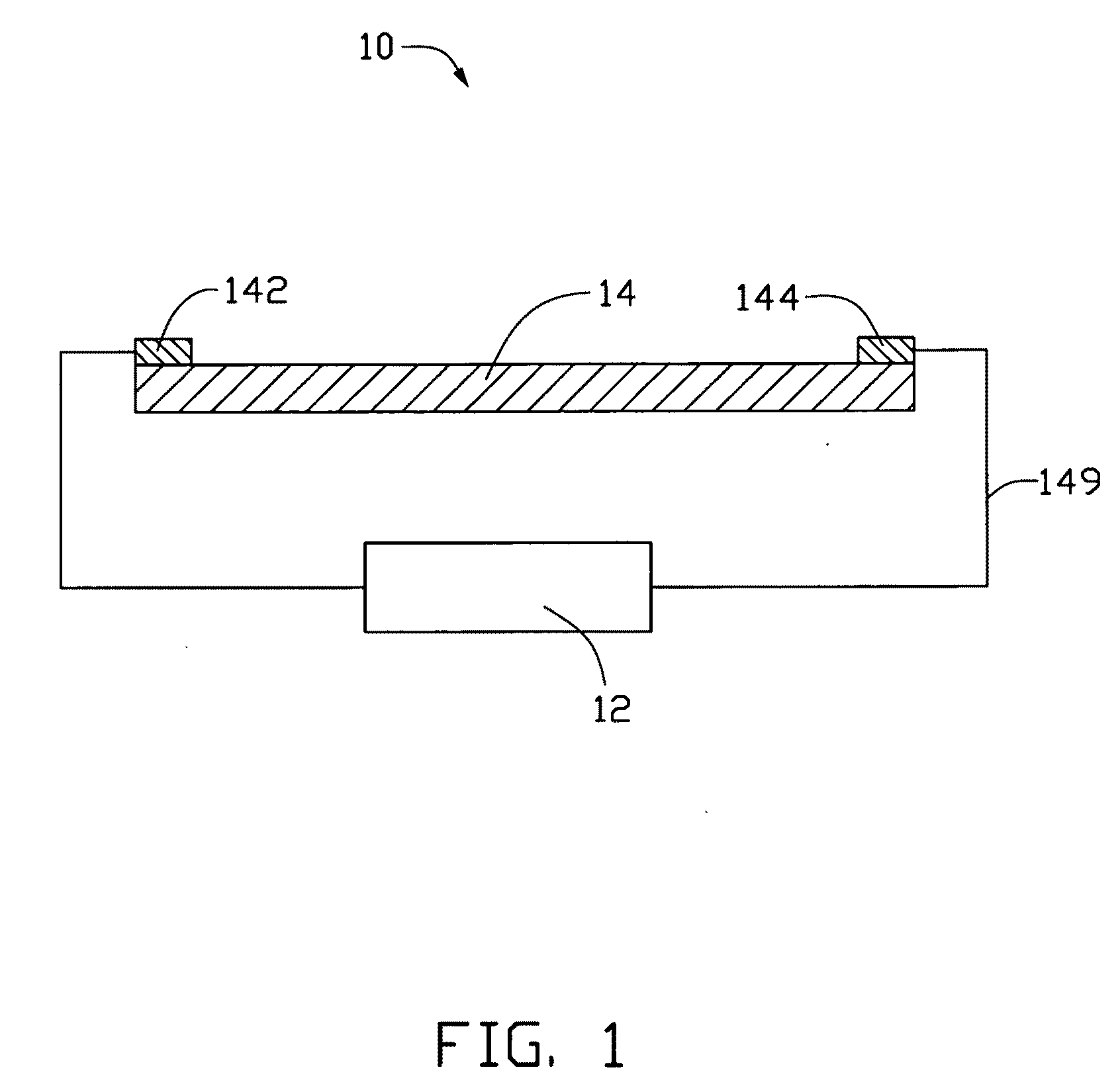
[0035]Referring to FIG. 1, a thermoacoustic device 10 according to one embodiment includes a signal device 12, a sound wave generator 14, a first electrode 142, and a second electrode 144. The first electrode 142 and the second electrode 144 are located apart from each other, and are electrically connected to the sound wave generator 14. In addition, the first electrode 142 and the second electrode 144 are electrically connected to the signal device 12. The first electrode 142 and the second electrode 144 input signals from the signal device 12 to the sound wave generator 14.

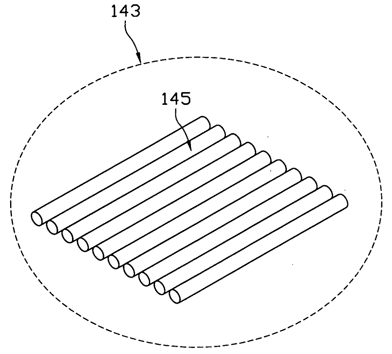
[0036]The sound wave generator 14 includes a carbon nanotube structure. The carbon nanotube structure can have a many different structures and a large specific surface area. The heat capacity per unit area of the carbon nanotube structure can be less than...


PUM

PropertyMeasurementUnit
frequencyaaaaaaaaaa
frequencyaaaaaaaaaa
thicknessaaaaaaaaaa

Abstract

A sound wave generator includes a carbon nanotube structure. The carbon nanotube structure includes one or more drawn carbon nanotube films. The one or more drawn carbon nanotube films produce sound by means of the thermoacoustic effect.

Description

RELATED APPLICATIONS[0001]This application is related to copending applications entitled, “THERMOACOUSTIC DEVICE”, filed ______ (Atty. Docket No. US20659); “THERMOACOUSTIC DEVICE”, filed ______ (Atty. Docket No. US20665); “THERMOACOUSTIC DEVICE”, filed ______ (Atty. Docket No. US20664); “THERMOACOUSTIC DEVICE”, filed ______ (Atty. Docket No. US20663); “THERMOACOUSTIC DEVICE”, filed ______ (Atty. Docket No. US20662); “THERMOACOUSTIC DEVICE”, filed ______ (Atty. Docket No. US20661); “THERMOACOUSTIC DEVICE”, filed ______ (Atty. Docket No. US20660); and “THERMOACOUSTIC DEVICE”, filed ______ (Atty. Docket No. US24929).BACKGROUND[0002]1. Technical Field[0003]The present disclosure relates to acoustic devices and method for generating sound waves, particularly, to a carbon nanotube based thermoacoustic device and method for generating sound waves using the thermoacoustic effect.[0004]2. Description of Related Art[0005]Acoustic devices generally include a signal device and a sound wave gene...

Claims


Application Information

Patent Timeline
Patent Type & Authority Applications(United States)
IPC IPC(8): H04B11/00
CPCH04R23/002Y10S977/902Y10S977/932
Inventor JIANG, KAI-LIXIAO, LINCHEN, ZHUOFENG, CHENFAN, SHOU-SHANYANG, YUAN-CHAO
Owner BEIJING FUNATE INNOVATION TECH
Why Eureka
Try Eureka