Eureka AIR delivers breakthrough ideas for toughest innovation challenges, trusted by R&D personnel around the world.

Acoustic System

Active Publication Date: 2009-10-29
HON HAI PRECISION IND CO LTD +1
View PDF47 Cites 45 Cited by
  • Summary
  • Abstract
  • Description
  • Claims
  • Application Information

AI Technical Summary

Problems solved by technology

However, the structure of the electric-powered loudspeaker 100 is dependent on magnetic fields and often weighty magnets.
However, in some conditions, the electrical signal may not available or desired.
The heating of the medium causes thermal expansion and produces pressure waves in the surrounding medium, resulting in sound wave generation.
However, the thermophone adopting the platinum strip, listened to the open air, sounds extremely weak because the heat capacity per unit area of the platinum strip is too high.
However, most of the sound pressures are not strong enough to be heard by human ear and must be detected by complicated sensors, and thus the utilization of the photoacoustic effect in loudspeakers is limited.

Method used


Image

  • Acoustic System
  • Acoustic System
  • Acoustic System

Examples


Embodiment Construction

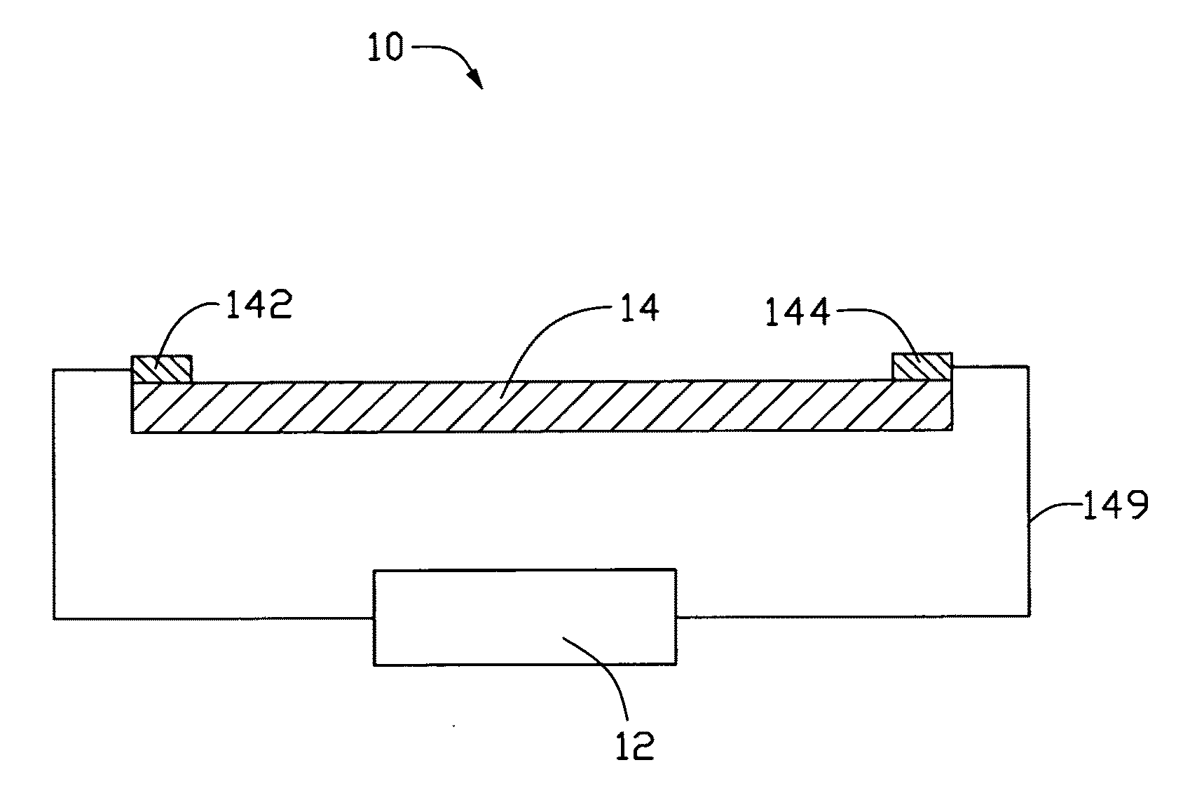
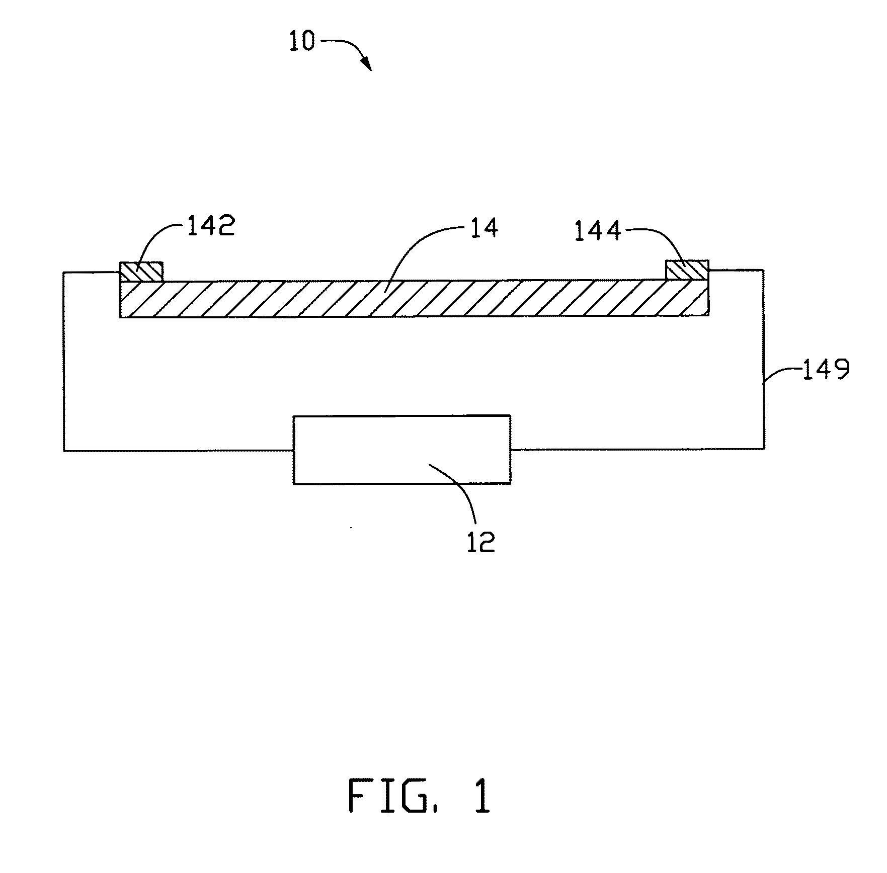
[0049]Reference will now be made to the drawings to describe, in detail, embodiments of the present thermoacoustic device, acoustic system, and method for generating sound waves.

[0050]Referring to FIG. 1, a thermoacoustic device 10 according to one embodiment includes a signal device 12, a sound wave generator 14, a first electrode 142, and a second electrode 144. The first electrode 142 and the second electrode 144 are located apart from each other, and are electrically connected to the sound wave generator 14. In addition, the first electrode 142 and the second electrode 144 are electrically connected to the signal device 12. The first electrode 142 and the second electrode 144 input signals from the signal device 12 to the sound wave generator 14.

[0051]The sound wave generator 14 includes a carbon nanotube structure. The carbon nanotube structure can have a many different structures and a large specific surface area (e.g., above 30 m2 / g). The heat capacity per unit area of the ca...


PUM


Abstract

An acoustic system includes a sound-electro converting device, a electro-wave converting device, and a sound wave generator. The electro-wave converting device is connected to the sound-electro converting device. The sound wave generator is spaced from the electro-wave converting device and includes a carbon nanotube structure. The sound-electro converting device converts a sound pressure to an electrical signal and transmits the electrical signal to the electro-wave converting device. The electro-wave converting device emits an electromagnetic signal corresponding to the electrical signal and transmits the electromagnetic signal to the carbon nanotube structure. The carbon nanotube structure converts the electromagnetic signal into heat, and the heat transfers to a medium causing a thermoacoustic effect.

Description

RELATED APPLICATIONS[0001]This application is related to copending applications entitled, “THERMOACOUSTIC DEVICE”, filed ______ (Atty. Docket No. US20654); “THERMOACOUSTIC DEVICE”, filed ______ (Atty. Docket No. US20651); “THERMOACOUSTIC DEVICE”, filed ______ (Atty. Docket No. US20652); “THERMOACOUSTIC DEVICE”, filed ______ (Atty. Docket No. US20655); and “METHOD AND DEVICE FOR MEASURING PROPERTIES OF ELECTROMAGNETIC SIGNAL”, filed ______ (Atty. Docket No. US20649).BACKGROUND[0002]1. Technical Field[0003]The present disclosure relates to acoustic devices, acoustic systems using the same, and method for generating sound waves, particularly, to a carbon nanotube based thermoacoustic device, an acoustic system using the same, and method for generating sound waves using the thermoacoustic effect.[0004]2. Description of Related Art[0005]An acoustic device generally includes a signal device and a sound wave generator. The signal device inputs electric signals into the sound wave generator...

Claims


Application Information

Patent Timeline
IPC IPC(8): B06B1/00
CPCH04R23/002B06B1/02
Inventor JIANG, KAI-LIXIAO, LINCHEN, ZHUOFAN, SHOU-SHANFENG, CHENYANG, YUAN-CHAO
Owner HON HAI PRECISION IND CO LTD
Why Eureka
Eureka Blog
Learn More