Conveyor device for powder materials

a conveying device and powder material technology, applied in the direction of conveying, bulk conveyors, transportation and packaging, etc., can solve the problems of deterioration of transport properties, inability to use uniform line segments over the conveying distance, insufficient supply of conveying gas, etc., to achieve the effect of reducing the energy required for transportation and reducing the gas consumption of bulk material fluidization

Inactive Publication Date:
View PDF8 Cites 14 Cited by
  • Summary
  • Abstract
  • Description
  • Claims
  • Application Information

AI Technical Summary

Benefits of technology

[0020]Fluidizing points, at which fluidizing gas is supplied via a fluidizing-gas connection, are expediently arranged further along the conveying path. The bulk material is kept in a liquefied state at said fluidizing points. As a result, the expenditure of energy required for transportation is reduced. In this case, a transverse feeding line is expediently provided, said transverse feeding line connecting a removal point to the conveying-gas connection at a fluidizing point placed further along the conveying path. The gas removed can therefore be supplied for further use, namely as a fluidizing gas. As a result, the gas consumption for the fluidizing of the bulk material is reduced. A more favourable method of implementation arises.
[0021]It has proven successful to arrange the removal points in an alternating manner with fluidizing points along the conveying pipe. The alternating sequence of gas supply and gas removal along the conveying line evens out the gas flow.

Problems solved by technology

In the case of longer conveying distances or in the case of more difficult transport conditions, it is generally inadequate to provide just one conveying-gas supply.
Disadvantages of this arrangement include the fact that it is highly complicated and that it is not possible to use uniform line segments over the conveying distance, but rather segments which are always different (becoming larger) have to be supplied and installed in some sections.
An increase in the diameter along the conveying line is not provided, and the gas volume which increases because of the supply of fluidizing gas therefore causes a deterioration in the transport properties.
There is the risk of the advantageous effect of the fluidization and therefore of the favourable conveying by the conveying gas being lost.

Method used


Image

  • Conveyor device for powder materials
  • Conveyor device for powder materials
  • Conveyor device for powder materials

Examples


Embodiment Construction

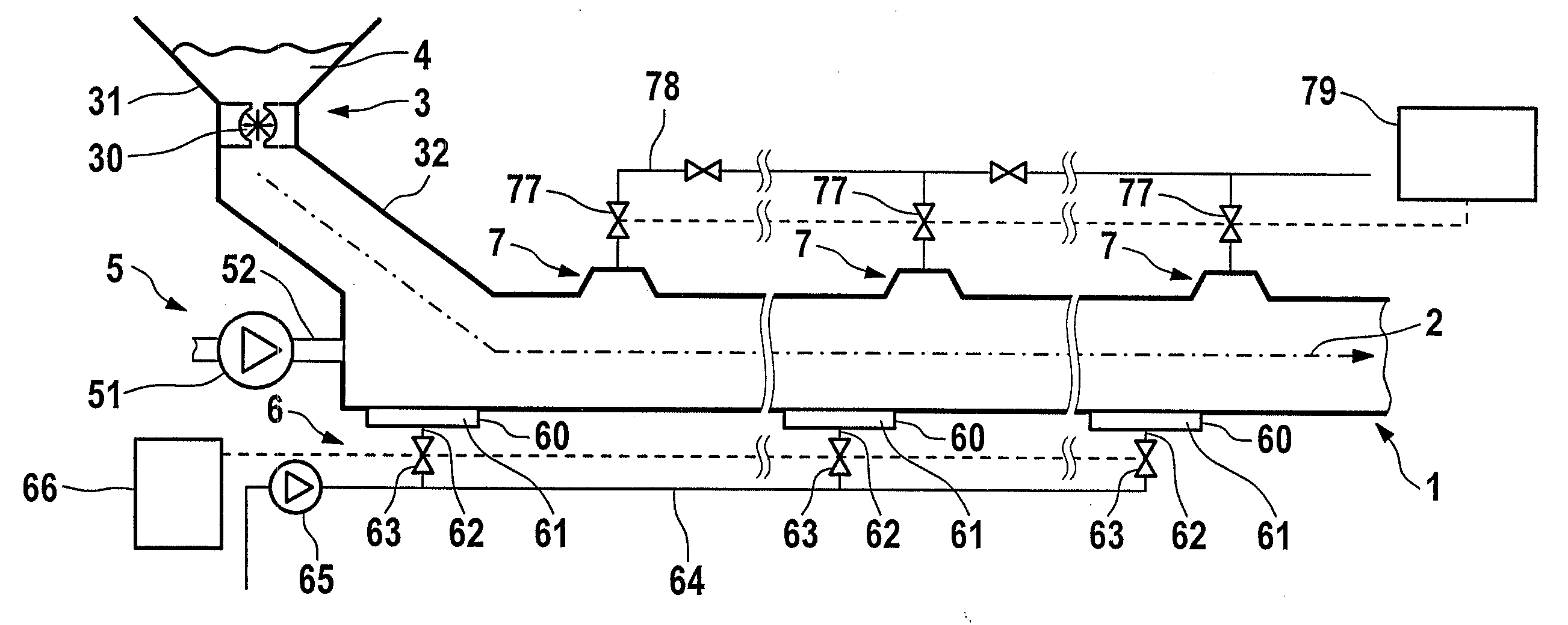
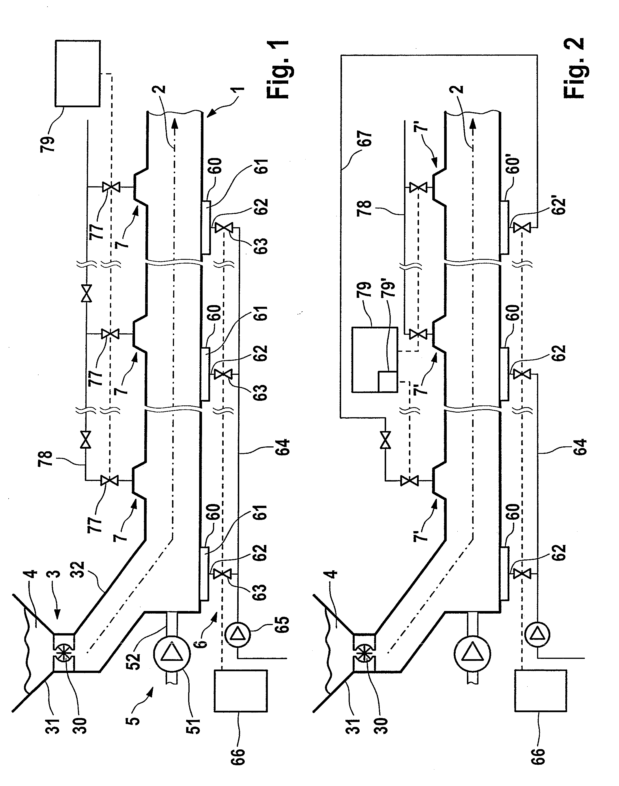
[0026]A pneumatic conveying apparatus is illustrated in the exemplary embodiment according to FIG. 1. It comprises an elongated conveying pipe 1 which defines a conveying path 2. A feeding-in point 3 for the bulk material 4 which is to be transported is arranged at the start of the conveying pipe 1. Said feeding-in point comprises a funnel-shaped container 31, at the lower pointed end of which a delivery line 32 leads obliquely downwards to the start of the conveying pipe 1. By means of said bulk-material feeding-in device 3, the bulk material 4 which is to be transported is introduced into the conveying pipe 3 of the conveying device via a pressure lock 30.

[0027]A supply device 5 for conveying gas is arranged at the start of the conveying pipe 1. Said supply device comprises a fan 51 which sucks up gas in a manner not illustrated specifically and blows it in via a short delivery line 52 at the beginning of the conveying pipe 1. The blowing-in operation expediently takes place paral...


PUM


Abstract

An apparatus for pneumatically conveying bulk material comprising a conveying pipe, a conveying gas source, and a plurality of removal points. The conveying pipe forms a conveying path for the bulk material. The conveying gas source is connected to the conveying pipe and is configured to supply conveying gas in the direction of the conveying path. The removal points allow gas to be removed from the conveying pipe. The removal points are arranged on the conveying pipe at a distance from one another along the conveying path, and are adjustable in terms of quantity of gas flow to be removed from the conveying pipe. Controlled removal of excess gas from the conveying pipe can therefore be achieved to reduce the gas velocity, such that the conveying remains steady and stable without a stepwise increase in the cross section of the conveying pipe along the conveying path.

Description

REFERENCE TO RELATED APPLICATIONS[0001]This application is a national stage application under 35 USC 371 of International Application No. PCT / EP2007 / 007638, filed Aug. 31, 2007, which claims priority of European Patent Application No. 06018220.1, filed Aug. 31, 2006, the contents of which are incorporated herein be reference in their entirety.FIELD OF THE INVENTION[0002]The invention relates to an apparatus for pneumatically conveying bulk material, with a conveying pipe which determines a conveying path for the bulk material, a conveying gas source which is connected to the conveying pipe and is designed for supplying conveying gas in the direction of the conveying path, and at least one removal point via which gas is removed from the conveying pipe.BACKGROUND OF THE INVENTION[0003]Conveying apparatuses with closed conveying lines for transporting bulk material, in particular pulverulent material, have long been known. A conveying-gas supply device is generally provided in order al...

Claims


Application Information

Patent Timeline
Patent Type & Authority Applications(United States)
IPC IPC(8): B65G53/40
CPCB65G53/28B65G53/20
Inventor HILGRAF, PETER
Why Eureka
Try Eureka