
Arrangement for automatic running gap control on a two or multi-stage turbine

a two or multi-stage turbine and automatic technology, applied in the direction of machines/engines, liquid fuel engines, lighting and heating apparatus, etc., can solve the problems of reducing and affecting the efficiency of the turbin

Inactive Publication Date: 2009-10-29
ROLLS ROYCE DEUT LTD & CO KG
View PDF8 Cites 11 Cited by
  • Summary
  • Abstract
  • Description
  • Claims
  • Application Information

AI Technical Summary

Benefits of technology

This solution provides a cost-effective, passive gap width control that maintains efficiency across all operating phases by automatically adjusting the gap width in response to thermal loads, ensuring optimal energy use and preventing rotor contact with stationary components.

Problems solved by technology

However, this is problematic in that the rotating and stationary components are subject to different dynamic loads and to different thermal loads, in particular in the various flight phases such as take-off, acceleration, continuous operation or deceleration, with their expansion and contraction characteristics deviating accordingly.
Under continuous operating conditions, this clearance will, however, grow to an extent that efficient use of the energy input is not ensured.
“Active” systems for running gap control are, however, disadvantageous in that they incur a loss of compressor work or a reduction of turbine efficiency, respectively.
Moreover, adequate control of the gap width between blade tips and liner segments is not possible in all operating phases.
Finally, active systems are expensive since they require valve and control devices.
The arrangement described in the above is, however, unsuitable for two or multi-stage turbines.

Method used


Image

  • Arrangement for automatic running gap control on a two or multi-stage turbine
  • Arrangement for automatic running gap control on a two or multi-stage turbine
  • Arrangement for automatic running gap control on a two or multi-stage turbine

Examples


Embodiment Construction

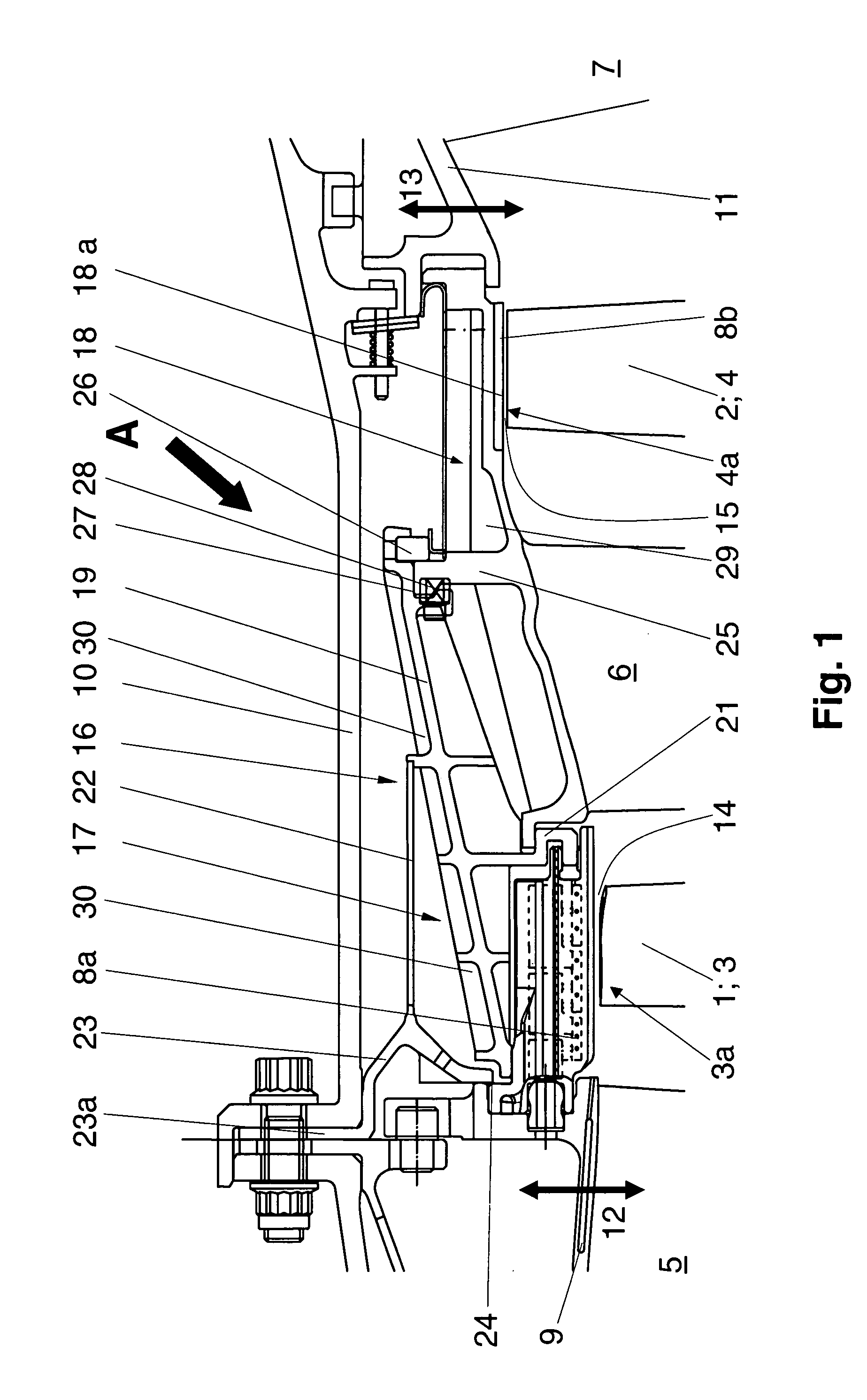
[0029]The two-stage turbine partially shown in FIG. 1 in schematic representation comprises a first rotor 1 and a second rotor 2, each with a row of rotor blades 3 or 4, respectively. A first or second stator vane row with first or second stator vanes 5, 6 respectively, is arranged upstream of the first or second rotor 1, 2, respectively. The principle of radial adjustment of the first and second shroud segments 8a, 8b forming a first and a second shroud and arranged remotely of the blade tips 3a, 4a is essentially identical with the design described in Specification GB-A-2061396 and is, therefore, not represented herein. This principle is only explained in that a one-piece expansion ring (not shown) is associated with each of the two rotors 1 and 2 of the two-stage turbine whose expansion behaviour agrees with that of the adjacent rotor 1 or 2, respectively. The expansion ring (not shown) associated with the first rotor 1 is connected to the first stator vanes 5, which are moveably...


PUM


Abstract

On a two or multi-stage turbine, expansion rings are provided in all stages at the sides of the rotors for passive, continuous running gap control whose thermal expansion and contraction behavior corresponds to that of the rotors and which are connected to radially moveable upstream and downstream stator vanes (5, 7). The downstream stator vanes are assembled to the upstream stator vanes via a bridge (16; 17, 18) which is axially and circumferentially fixed and located flexibly in the radial direction on the outer casing (10) of the turbine. The stator vanes (6) arranged between the rotor disks are integrally connected to the bridge or, as separate components, held axially and circumferentially on the bridge to take up rolling and tilting moments.

Description

[0001]This application claims priority to German Patent Application DE 10 2004 016 222.0 filed Mar. 26, 2004, the entirety of which is incorporated by reference herein.BACKGROUND OF THE INVENTION[0002]This invention relates to an arrangement for automatic—passive—running gap control on a two or multi-stage turbine which comprises at least first and second rotors within an outer casing, with stator vanes arranged upstream, between and downstream of these rotors, respectively.[0003]On the turbine of aircraft engines, the clearance between the blade tips of the rotor and the casing adjacent to it or another stationary component are desirably kept as small as possible to minimize performance and fuel losses and ensure high efficiency of the engine in all flight phases. However, this is problematic in that the rotating and stationary components are subject to different dynamic loads and to different thermal loads, in particular in the various flight phases such as take-off, acceleration,...

Claims


Application Information

Patent Timeline
Patent Type & Authority Applications(United States)
IPC IPC(8): F01D11/00F01D9/00F01D11/16F01D11/18F01D11/24F01D25/26F28F7/00
CPCF01D11/18F05D2240/11F01D25/26F01D11/24
Inventor WUNDERLICH, THOMASSCHIEBOLD, HARALDBROADHEAD, PETER
Owner ROLLS ROYCE DEUT LTD & CO KG
Features
  • Generate Ideas
  • Intellectual Property
  • Life Sciences
  • Materials
  • Tech Scout
  • Unparalleled Data Quality
  • Higher Quality Content
  • 60% Fewer Hallucinations
Learn More