Dynamic Damper

a damper and dynamic technology, applied in the field of dynamic dampers, can solve the problems of reducing working efficiency, water entering the clearance, increasing the force required to press, etc., and achieve the effects of preventing deformation of the thin-walled portion, preventing deterioration of the characteristics of the dynamic damper, and improving the attachment of the rotational shaft along the main body

Active Publication Date: 2009-10-29
HONDA MOTOR CO LTD
View PDF5 Cites 3 Cited by
  • Summary
  • Abstract
  • Description
  • Claims
  • Application Information

AI Technical Summary

Benefits of technology

[0018]Thus, in the present invention, the attachment of the rotational shaft along the main body can be improved, and the deformation of the thin-walled portion can be prevented, so that deterioration of the characteristics of the dynamic damper can be prevented.
[0019]Further, in the present invention, the rotational shaft is preferably press-fitted in the through hole from the one end with the inner diameter D2 to the other end with the inner diameter D3. In this case, tight sealing can be achieved between the rotational shaft and a first hole portion in the vicinity of the one end with the smaller inner diameter and between the rotational shaft and a second hole portion in the vicinity of the other end with the larger inner diameter on which the band is tightened, so that the water penetration can be prevented effectively at both ends.

Problems solved by technology

Heretofore, there is known a dynamic damper mounted on a rotational shaft such as a drive shaft or a propeller shaft of an automobile, for damping hazardous vibrations which should not be caused, such as flexural vibrations, torsional vibrations, etc. that are developed due to an unbalanced rotational behavior caused when the rotational shaft rotates.
However, the dynamic dampers disclosed in Patent Documents 1 and 2 are disadvantageous in that water may penetrate into a clearance between the rotational shaft and the inner wall surface of the boss in a portion where the fixing band is not tightened on the boss.
However, in this case, an increased force is required to press-fit the rotational shaft into the boss against the inner wall surface thereof when the dynamic damper is mounted on the rotational shaft.
Thus, the working efficiency is reduced, and an additional press-fit apparatus or the like is required other than existing facilities, resulting in higher production costs.
Further, when the increased force is applied to press-fit the rotational shaft into the boss, against the inner wall surface thereof the inner wall of the boss is excessively stressed and deformed.

Method used


Image

  • Dynamic Damper
  • Dynamic Damper
  • Dynamic Damper

Examples


Embodiment Construction

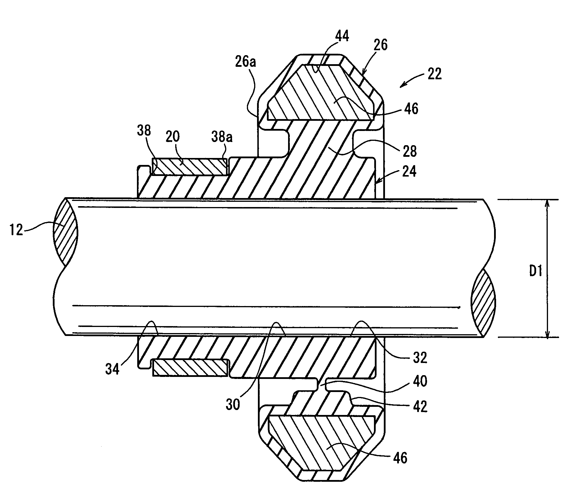
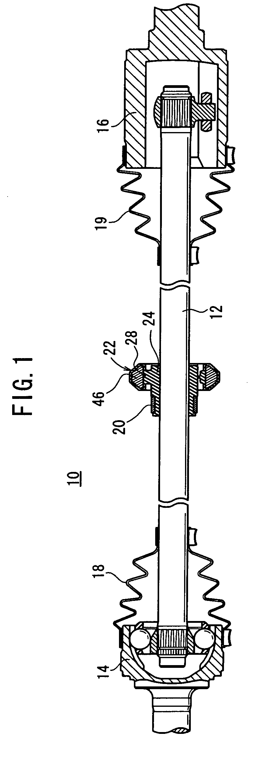
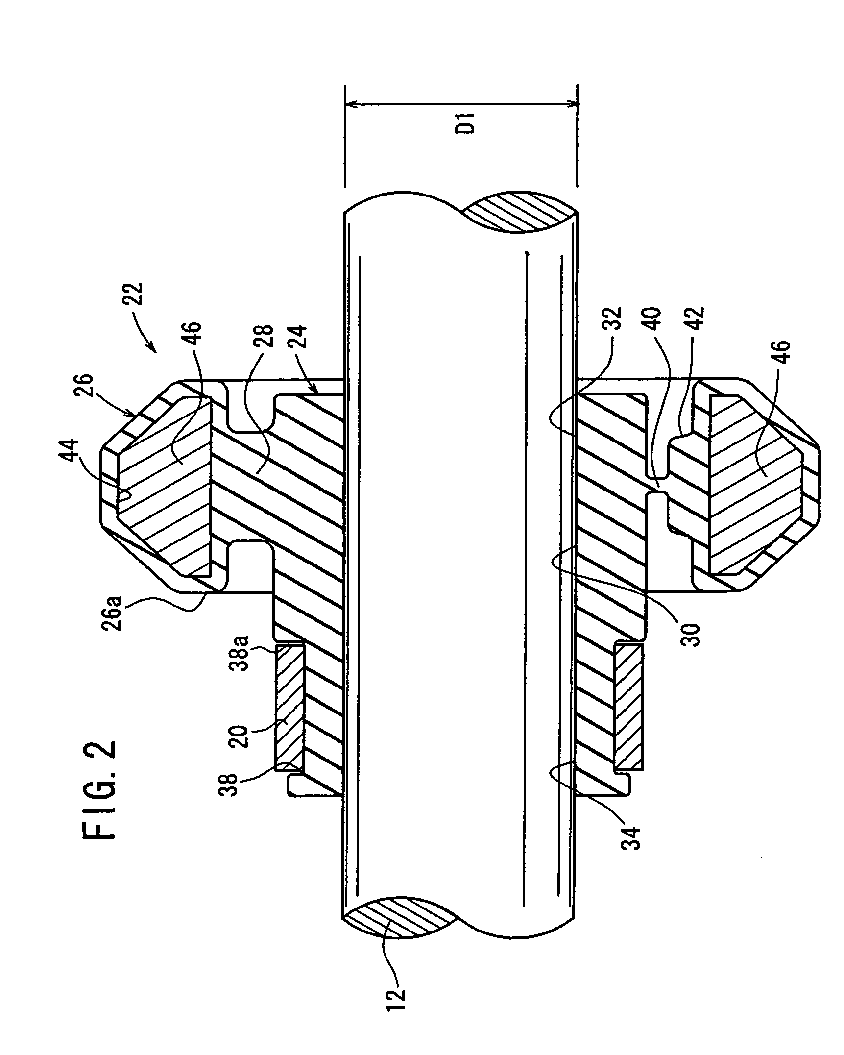
[0032]FIG. 1 is a vertical cross-sectional view, partly omitted from illustration, of a drive force transmitting mechanism in which a dynamic damper according to an embodiment of the present invention is mounted on a drive shaft as a rotational shaft, and FIG. 2 is an enlarged vertical cross-sectional view of the dynamic damper mounted on the drive shaft.

[0033]The drive force transmitting mechanism 10 contains a drive shaft 12 having an outer diameter D1 as shown in FIG. 2, and a Barfield constant velocity universal joint 14 and a tripod constant velocity universal joint 16 which are joined to the respective ends of the drive shaft 12. Joint boots 18, 19 made of rubber or resin are mounted respectively on the Barfield constant velocity universal joint 14 and the tripod constant velocity universal joint 16. A dynamic damper 22 is mounted substantially centrally on the drive shaft 12 by a band 20 such as a stainless steel band.

[0034]As shown in FIGS. 3 and 4, the dynamic damper 22 has...


PUM


Abstract

A dynamic damper in which the inner diameter (D2) of a first hole part formed at the axial one end part of a body part overlapped with a weight part in the radial direction is set smaller than the inner diameter (D3) of a second hole part formed at the axial other end part of the body part not overlapped with the weight part in the radial direction and tightened with a band member (D3>D2). The outer diameter (D1) of a drive shaft to be press-fitted into the first and second hole parts is set larger than the inner diameter (D2) of the first hole part and the inner diameter (D3) of the second hole part (D1>D3>D2).

Description

TECHNICAL FIELD[0001]The present invention relates to a dynamic damper mounted on a rotational shaft such as a drive shaft of an automobile, for damping hazardous vibrations developed on the rotational shaft.BACKGROUND ART[0002]Heretofore, there is known a dynamic damper mounted on a rotational shaft such as a drive shaft or a propeller shaft of an automobile, for damping hazardous vibrations which should not be caused, such as flexural vibrations, torsional vibrations, etc. that are developed due to an unbalanced rotational behavior caused when the rotational shaft rotates.[0003]The dynamic damper has a function to absorb the vibrational energy of the rotational shaft by converting the vibrational energy into vibrational energy of the dynamic damper by way of resonance, with the natural frequency of the dynamic damper being equal to the dominant frequency of excited hazardous vibrations of the rotational shaft.[0004]One dynamic damper of the above type, which is disclosed in Patent...

Claims


Application Information

Patent Timeline
Patent Type & Authority Applications(United States)
IPC IPC(8): F16F15/10F16F15/12F16F7/00
CPCY10T464/50F16F15/1442F16C2326/06F16C3/02F16F15/10
Inventor KAWAKATSU, TSUTOMUNAKAO, SHOUICHISUZUKI, SUSUMUKURIHARA, TAKAO
Owner HONDA MOTOR CO LTD
Why Eureka
Try Eureka