Ultrasound diagnosis apparatus

a technology of ultrasound and diagnostic equipment, applied in the field of ultrasound diagnosis equipment, can solve the problems of difficult to distinguish between a displacement caused by tissue motion and a displacement caused by radiation force, and the difficulty of applying the method to a region far from a body surface which a force does not cover well

Active Publication Date: 2009-10-29
HITACHI LTD
View PDF3 Cites 10 Cited by
  • Summary
  • Abstract
  • Description
  • Claims
  • Application Information

AI Technical Summary

Benefits of technology

[0009]Thus it is possible to extract a tissue expansion caused by a thermal denaturation generated on a part of a patient by a radiation of a therapeutic converging beam.
[0010]According to the present invention, it is possible to extract a tissue expansion caused by a thermal denaturation generated on a region remote from a body surface of a patient.

Problems solved by technology

When an elastic modulus imaging method is used in monitoring a minimally invasive treatment, it is difficult to apply the method to a region far from a body surface which a force does not cover well because of a necessity of a pressurization from outside.
On one hand, in an imaging method using the radiation force, when a patient is moving by a tissue motion such as a respiration, it is difficult to distinguish between a displacement caused by the tissue motion and that caused by the radiation force.

Method used


Image

  • Ultrasound diagnosis apparatus
  • Ultrasound diagnosis apparatus
  • Ultrasound diagnosis apparatus

Examples


first embodiment

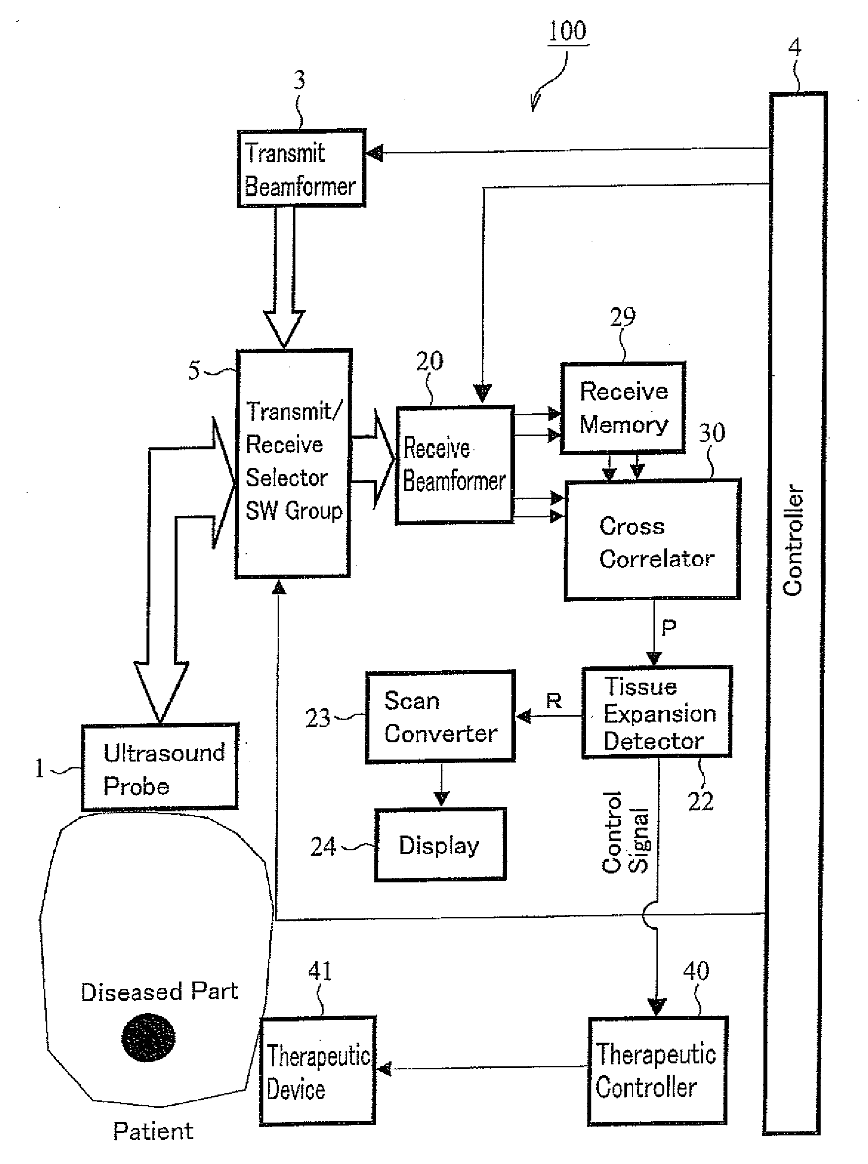
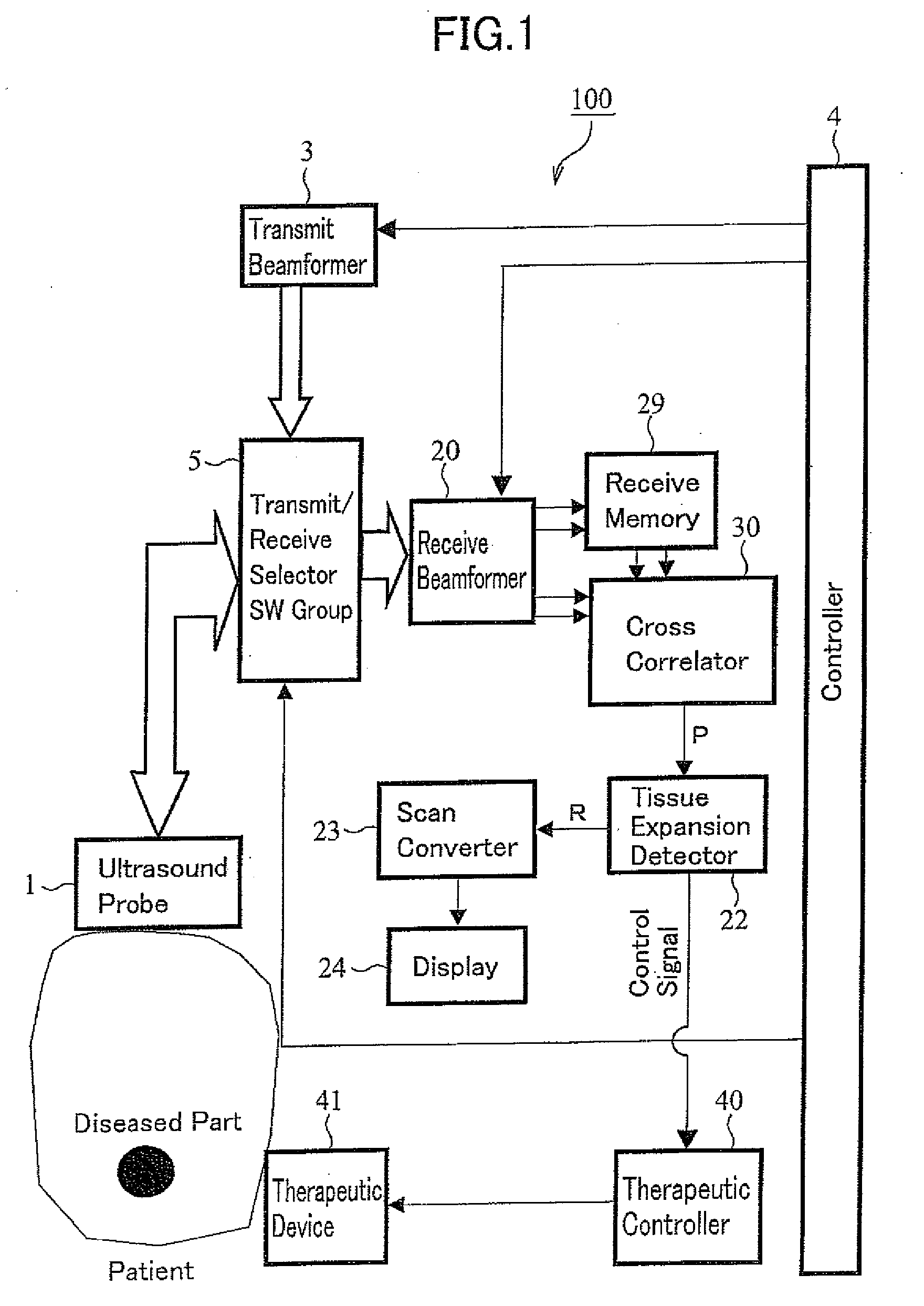
[0025]FIG. 1 is a configuration drawing of an ultrasound diagnosis apparatus of an embodiment of the present invention.

[0026]An ultrasound diagnosis apparatus 100 includes an ultrasound probe 1 for converging and radiating an ultrasound on a diseased part of a patient and performing a heating coagulation therapy; and an ultrasound imaging device for using an ultrasound echo and imaging the patient, wherein the ultrasound probe 1 consists of a therapeutic device 41 and a therapeutic controller 40. In addition, as the therapeutic device 41, it is also possible to use an RF therapeutic probe for radiating an electromagnetic wave such as an RF beam and a microbeam. In addition, the ultrasound imaging device extracts a change of an acoustic impedance of a patient as an differentiation image, and comprises: the ultrasound probe 1; a transmit / receive selector SW (Switch) group 5; a transmit beamformer 3; a receive beamformer 20; a beam receiving memory 29; a cross correlator 30 of an opera...

second embodiment

[0046]Although in the first embodiment the tissue expansion is detected by calculating the ultrasound radial component of a displacement and by obtaining a difference between the ultrasound radial component and an integral amount thereof, it is also possible to detect the tissue expansion by operating a cross correlation between a displacement and a template of a tissue expansion.

[0047]FIGS. 9A and 9B are configuration drawings of the expansion detector 22 for performing a cross correlation with a template; FIG. 9A shows an configuration of an expansion detector 22b for performing a cross correlation in a time domain; and FIG. 9B shows an configuration of an expansion detector 22c for performing a cross correlation in a frequency domain.

[0048]By a cross correlator 62, the expansion detector 22b performs in the time domain a cross correlation between the displacement signal P from the cross correlator 30 and a displacement function 61, where a displacement form characteristic of a ti...

third embodiment

[0054]In the embodiments, although the methods of distinguishing the radiation force and the tissue expansion in a signal processing unit are described, it is also possible to suppress a displacement caused by the radiation force and to stand out a displacement caused by the tissue expansion depending on a treatment method if any.

[0055]In FIG. 12 is shown a configuration drawing of an ultrasound diagnosis apparatus of a third embodiment. To the same elements as in FIG. 1 are appended the same symbols; descriptions thereof will be omitted and only different points thereof will be described.

[0056]In the embodiment the therapeutic device 41 of a transmit transducer is divided into two piezoelectric devices 42a, 42b, and a transmitter 43 uses a signal from the therapeutic controller 40 and drives the devices 42a, 42b.

[0057]As shown in FIG. 13A, each of the piezoelectric devices 42a, 42b mutually inverts therapeutic ultrasound beams like semicircles in their phases, and converges and ra...


PUM


Abstract

An ultrasound diagnosis apparatus includes an ultrasound probe 1, in which a plurality of transducer elements are arrayed and which converges and radiates an ultrasound on a patient and detects a reflection wave thereof, and images a tomogram of the patient, using the reflection wave, wherein an expansion detector 22 operates a difference between a radial component of a therapeutic converging beam of a movement amount of each part, and an integral amount integrated from the radial component, and extracts a tissue expansion generated at a part of the patient from the tomogram, and wherein the movement amount is calculated by performing a pattern matching between tomograms imaged with different frames.

Description

TECHNICAL FIELD[0001]The present invention relates to an ultrasound diagnosis apparatus for using an ultrasound probe and diagnosing a patient.BACKGROUND ART[0002]Heating coagulation therapies are methods of thermally treating a malignant tumor such as a prostrate cancer, a liver cancer, and a breast cancer; and a diseased part such as a uterine myoma and a prostrate hypertrophy by radiating a strong converging ultrasound beam radiation or an electromagnetic wave such as an RF (Radio Frequency) beam and a microbeam. These treatment methods enable a therapy without an incision of a body surface, and therefore, their application to clinical practice is enlarging as a minimally invasive treatment method.[0003]Furthermore, an ultrasound imaging method makes it possible to observe a tomogram of a living body in real time; however, it images only a region of not less than a boiling point, and it is difficult to image a protein denaturation region of 60 Celsius degrees to less than 100 Cel...

Claims


Application Information

Patent Timeline
Patent Type & Authority Applications(United States)
IPC IPC(8): A61B8/13
CPCA61B8/0833A61B8/14A61B8/483A61B8/485G01S15/899A61N7/02A61N2007/0078G01S7/52036G01S7/52042A61B18/14
Inventor AZUMA, TAKASHIUMEMURA, SHINICHIRO
Owner HITACHI LTD
Why Eureka
Try Eureka